Steemian Friends,
Today, I will write a tutorial about Industrial Electrical. As we become electrical engineers, we know theory best, but our practical knowledge is very limited. I will write one electrical topic every week to teach electrical engineers or users working with industrial electricals from my experience. Hopefully, everyone can learn by reading my writing.
Design By Canva
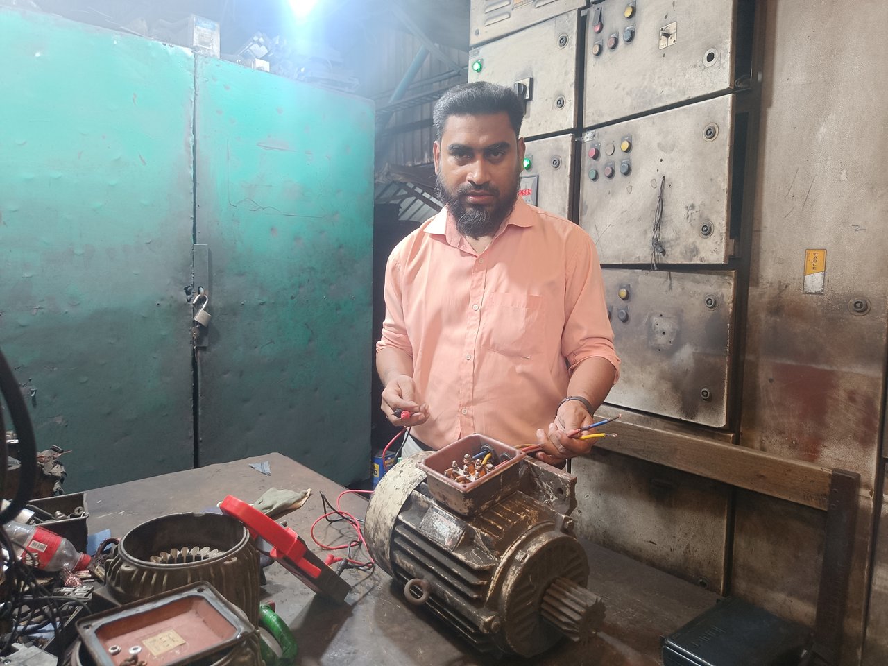
Today, I will teach the technique of checking the star connection of a three-phase induction motor and testing the motor with a multimeter. I work in an industrial electrical department. I think the most important job of an electrical engineer is the topic of my writing today, so let's begin.
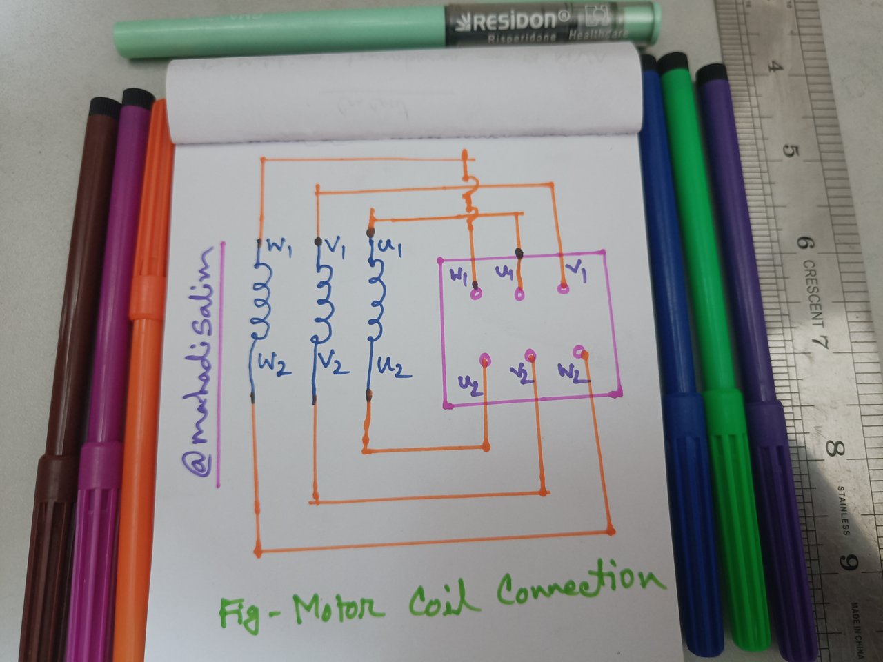
First, I have drawn the coil connection diagram of a three-phase induction motor. This diagram is read in every electrical engineering book, so I drew it. Here, coils u1,v1, and w1 have one end. The other three coil ends are named u2,v2, and w2. An induction motor has six terminals inside. I have drawn a picture below.
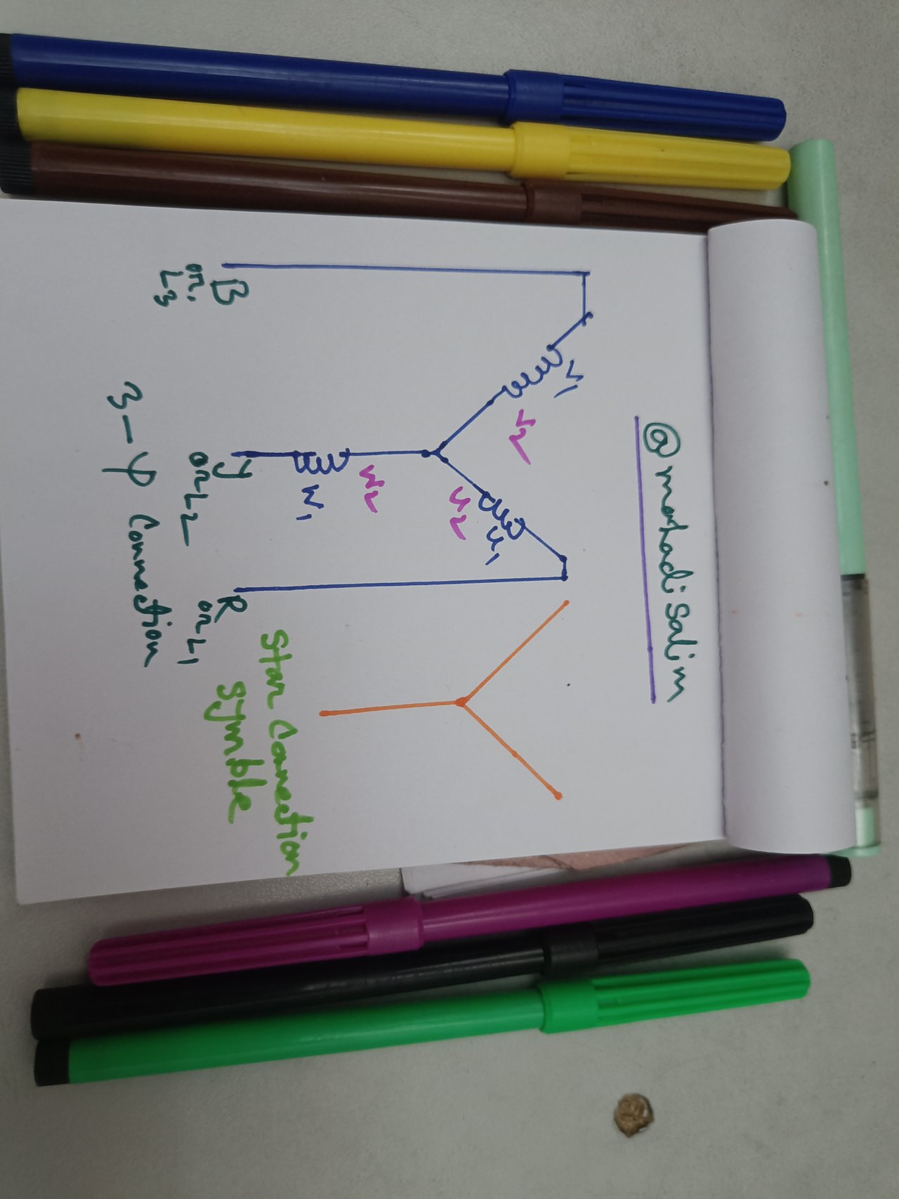
Then, I drew a diagram showing the star connection of my current induction-type motor. Here are the symbols for star connection and coil connection. There are three coil connections with two terminals each. One coil is labelled as u1 and u2, the second as v1 and v2, and the third as w1 and w2. It is shown in the picture below.
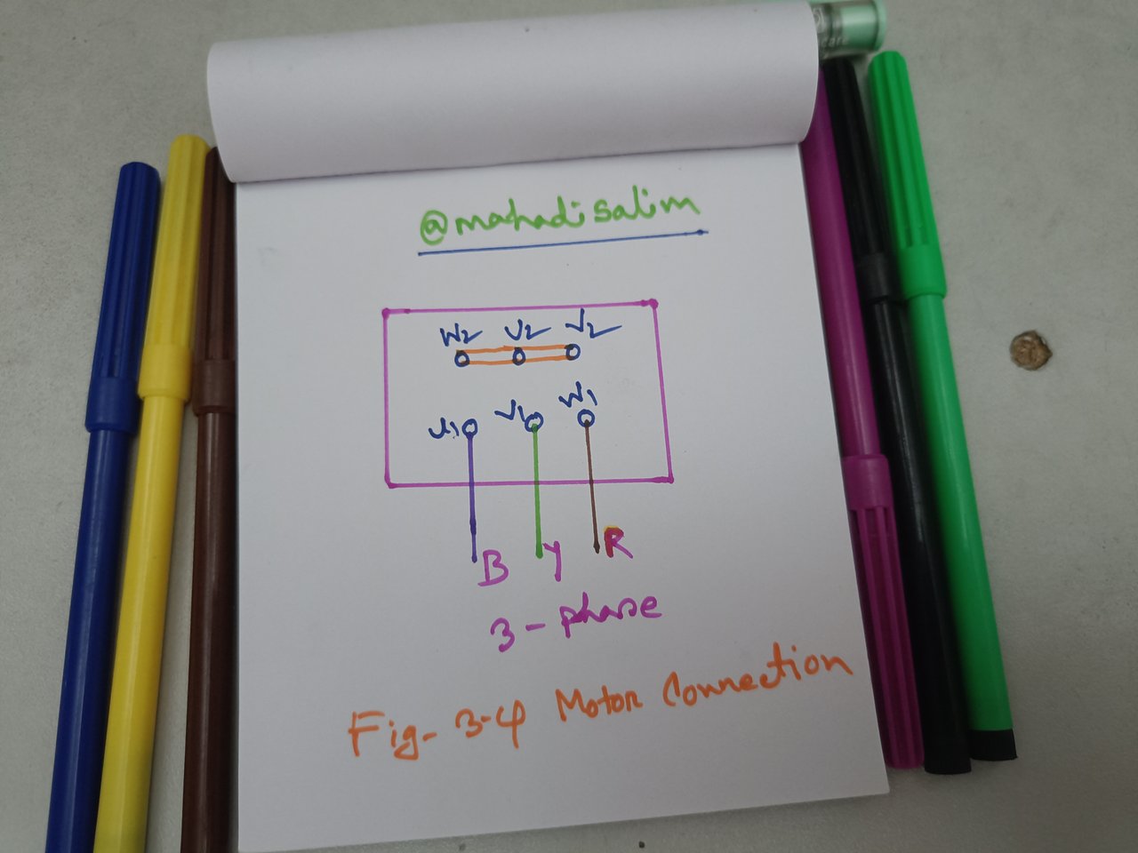
Then, I have drawn the connection diagram of an induction type motor. Here, the connections of u2,v2, and w2 coils are joined to a point. Three-phase Red, Yellow, and Blue wires are connected from the other three ends, u1,v1, and w1. Basically, it is a star connection of an induction-type motor.
Now, I will show the above diagrams practically while working in the electrical industry. Then, everyone can learn theory as well as practice.
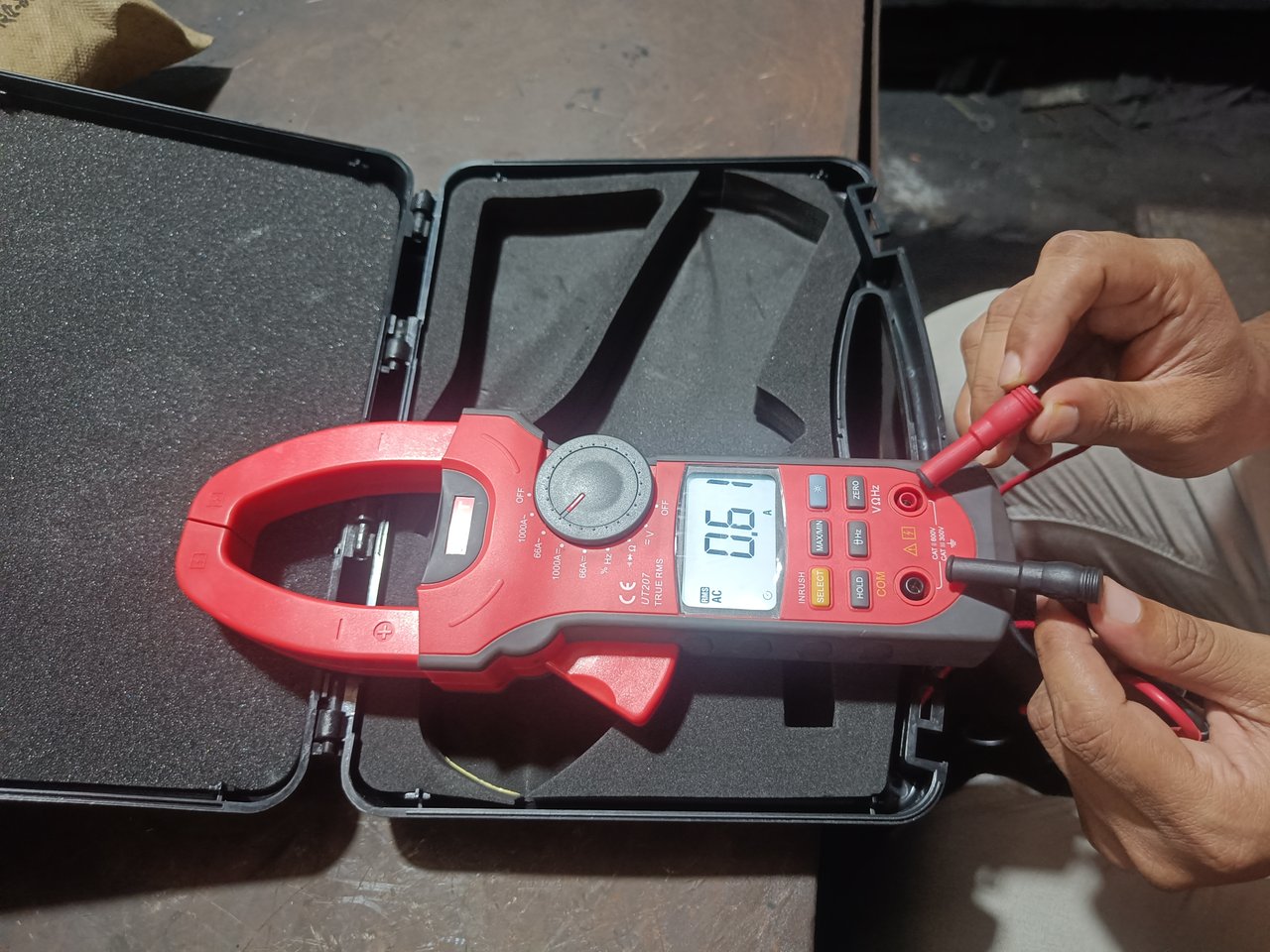
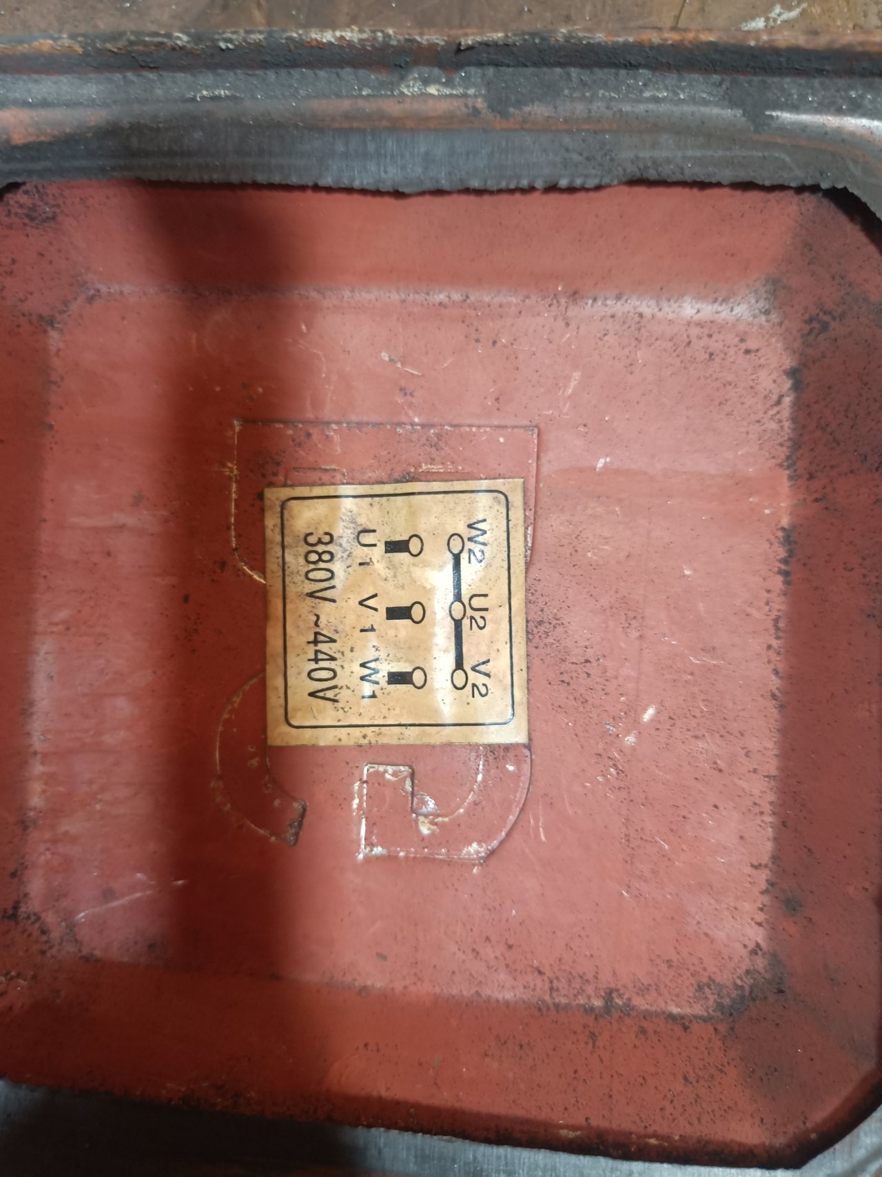
I have a three-phase induction motor and a multimeter. Then, I opened the motor's terminal box and took a picture of the star connection drawing, which is exactly the same as my diagram above.
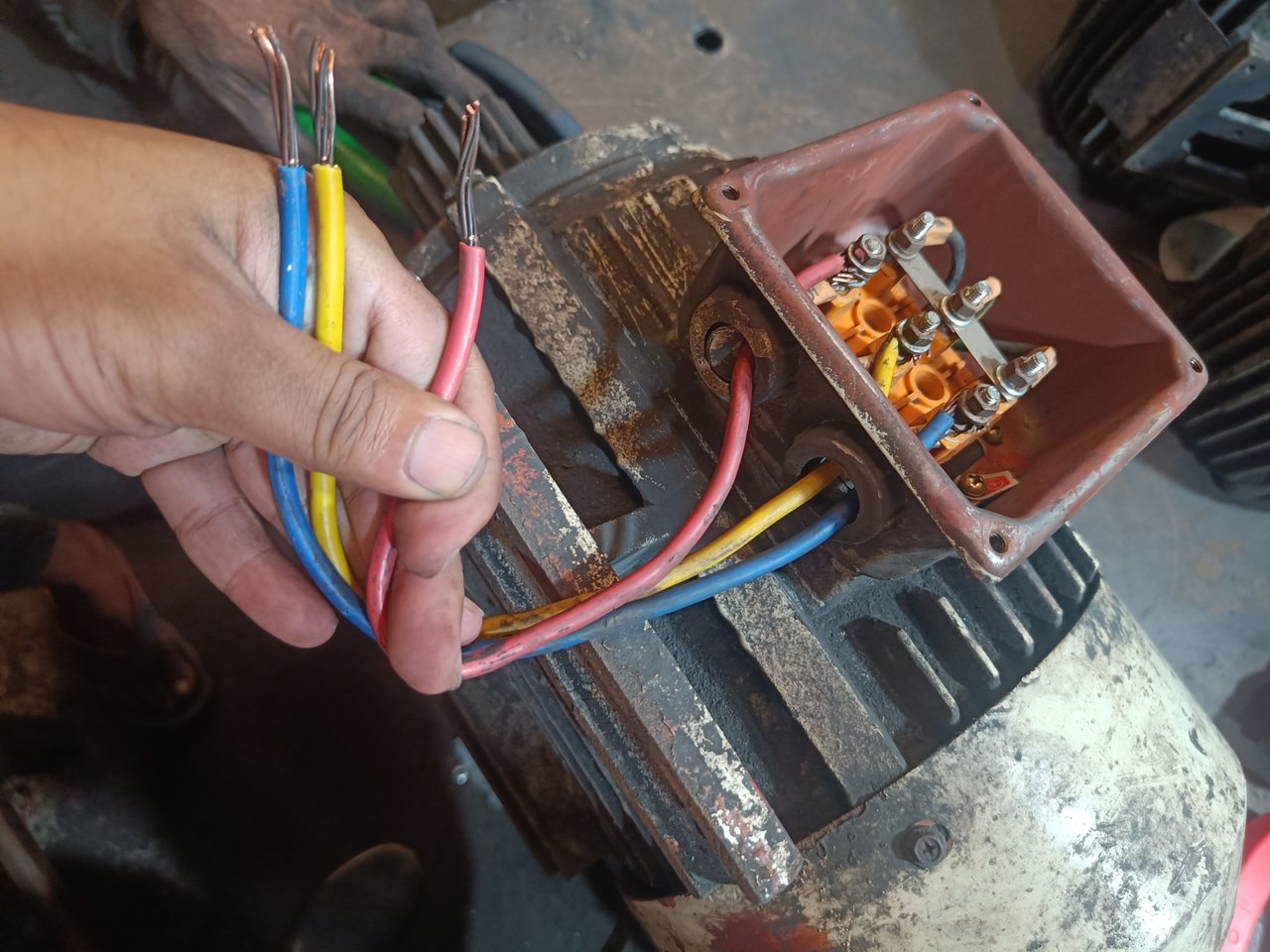
Then, I removed three wires from the u1,v1, and w1 terminals of the motor by connecting red, yellow, and blue, respectively. I connected the other three ends, u2,v2, and w2, together with a copper bar, which corresponds to my diagram above.
Then I take a multimeter and set the selector switch to the ohms end. Then I hold the knob of the multimeter to the u1 and u2 ends and see the display of the multimeter. Thus, check v1, v2, and w1; w2 ends in the same way as a multimeter. Since these terminals are the same as the motor coil connection, the meter shows ohms. This made me realize that my motor is fine.
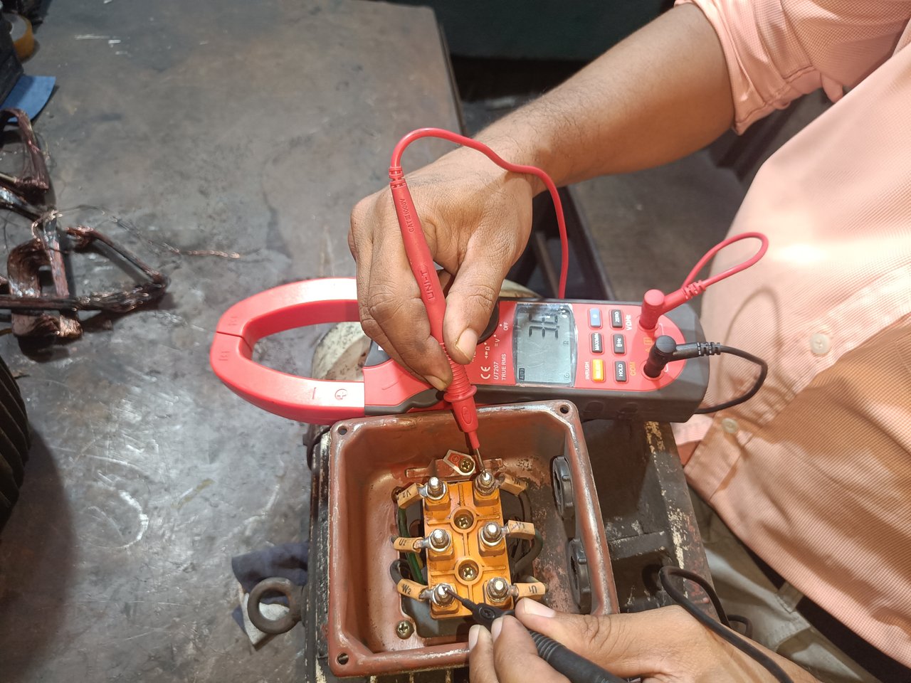
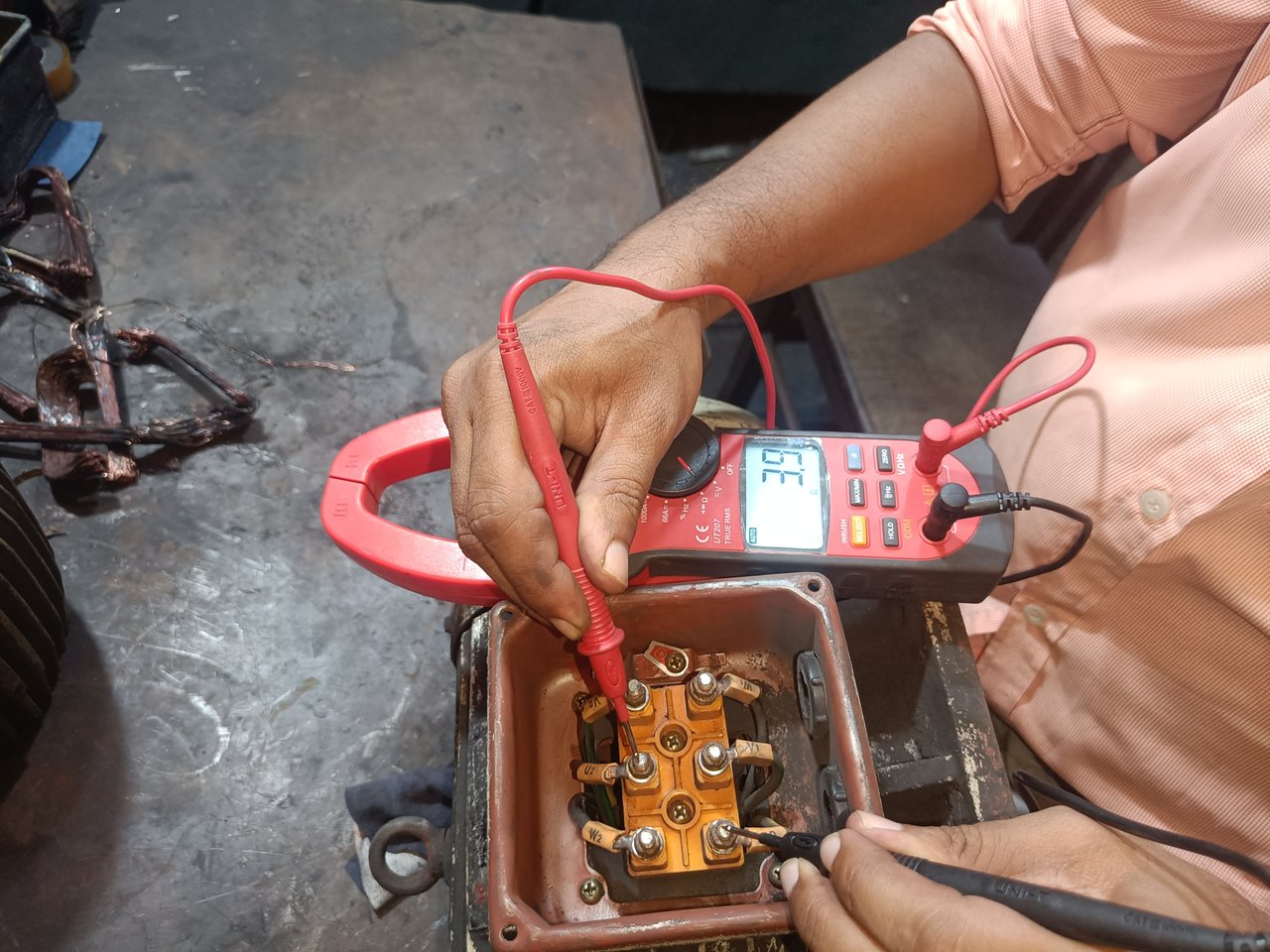
Then, I checked u1 and v1, u2 and v2, and w1 and w2 with a multimeter. This is shown in the picture below. Since the upper ends are not connected, the multimeter does not show ohms.
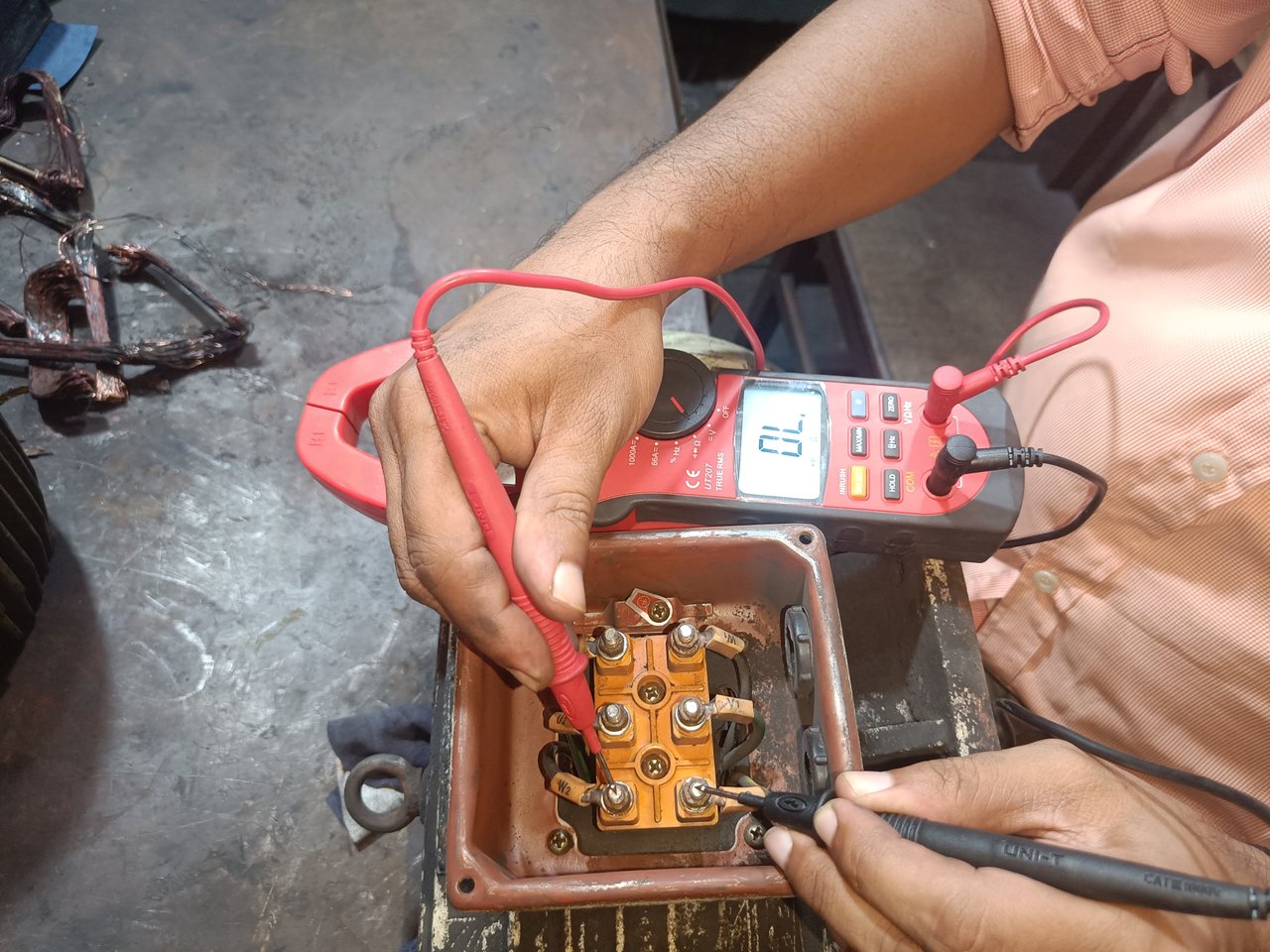
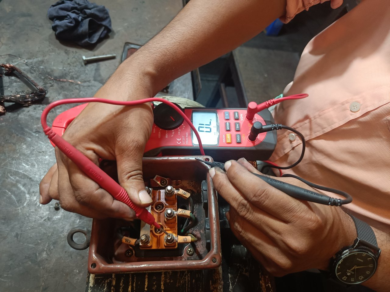
Then, I check each terminal by holding one knob on the multimeter and the other knob on the motor body. If the motor coil is sticking to the motor body, this test will detect it. I have shown it in the picture below.
In the next tutorial, I will show the delta connection of an induction-type motor and techniques for checking the motor. I hope that by reading my article, you have learned how to connect and troubleshoot a three-phase induction motor.


