Steemian Friends,
Today, I will write my Industrial Electrical Lessons Part 02. In the last learning part, I have shown the star connection of a three-phase induction motor and the technique of checking the motor with a multimeter. Today, I will show the delta connection of a three-phase induction motor and the technique of checking the motor with a multimeter. Hopefully, an electrical engineer or technician reading my post can make and check the star and delta connections of the motor.
.png)
Design By Canva
I have first shown the delta connection symbol of a motor and the coil connection. Among the six ends of the motor coil, two ends are connected to one point. In this way, three ends named R, Y, and B have been removed by connecting the two ends, which I have shown in the picture below.
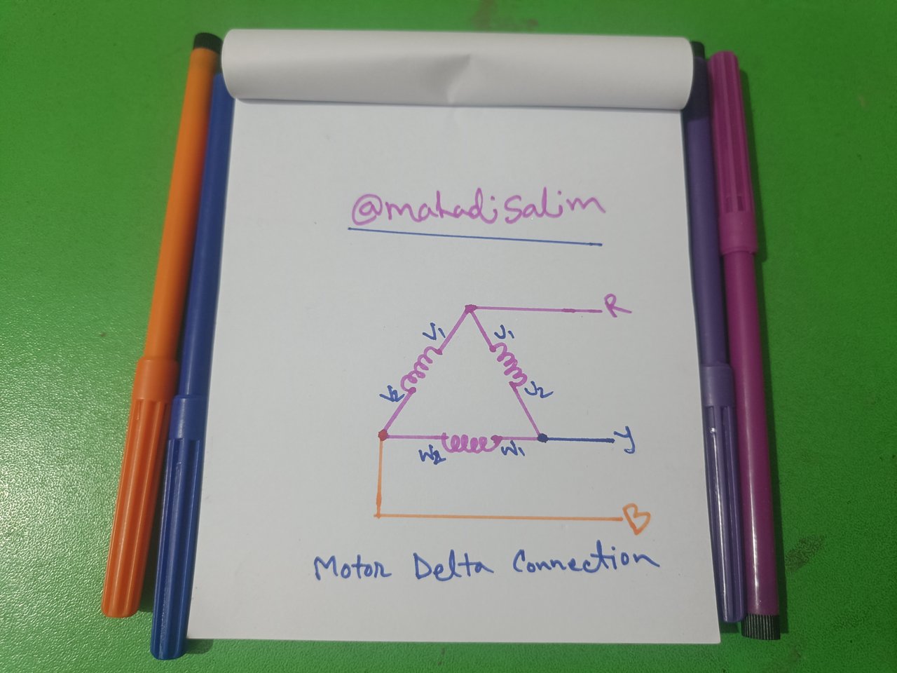
Motor Delta coil connection
Then, I diagrammed the delta connection of the six terminals of the motor's connector box. In the figure, three cables are taken out from U1, V1, and W1 ends, respectively Red, Yellow, and Blue, which will be three-phase power supply input. Then, three copper bars were connected to U1 & W2, V1 & U2, and W1 & V2, which I have shown in the picture below.
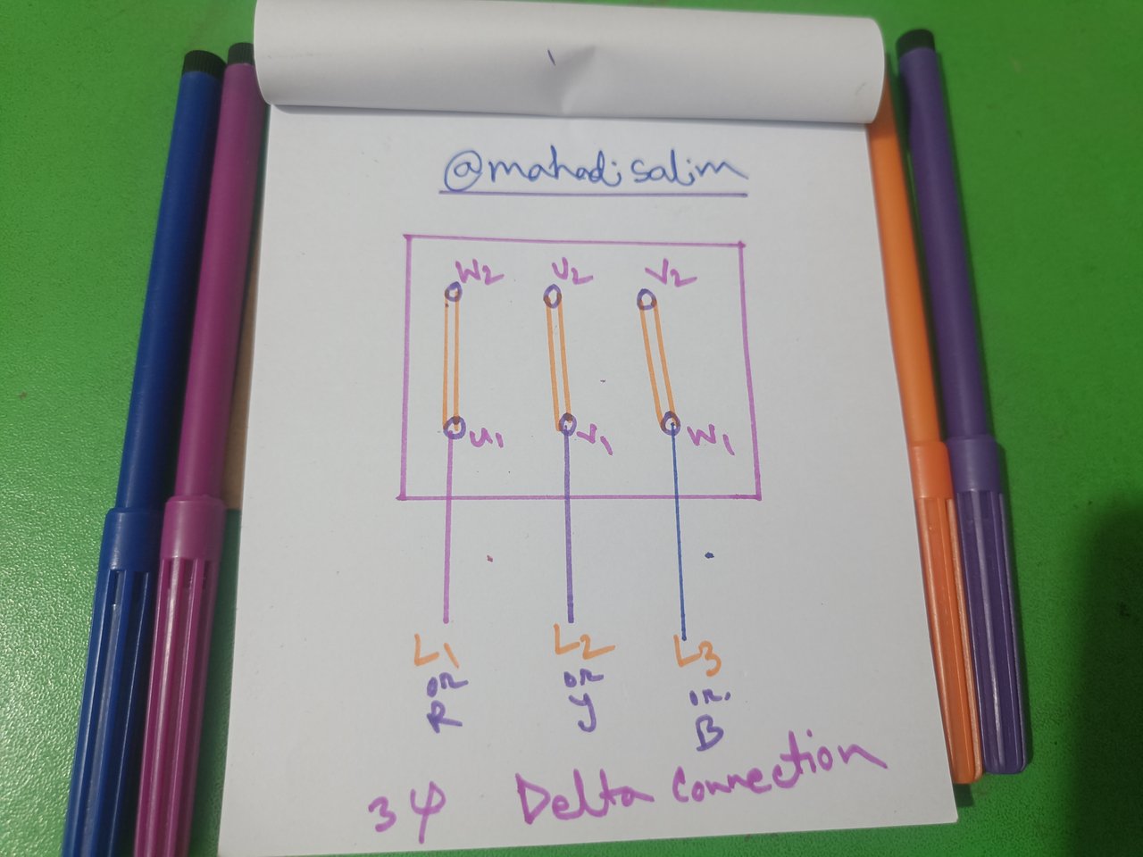
First, I took a three-phase induction-type motor and a multimeter. Then, I opened the motor's connector box and showed the connection diagram that matched my drawing. Then, I looked at the drawing of the motor's connector box and showed the actual connection below.
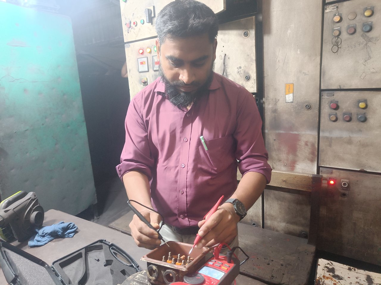
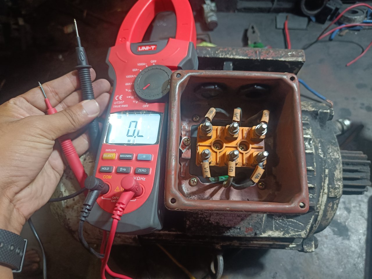
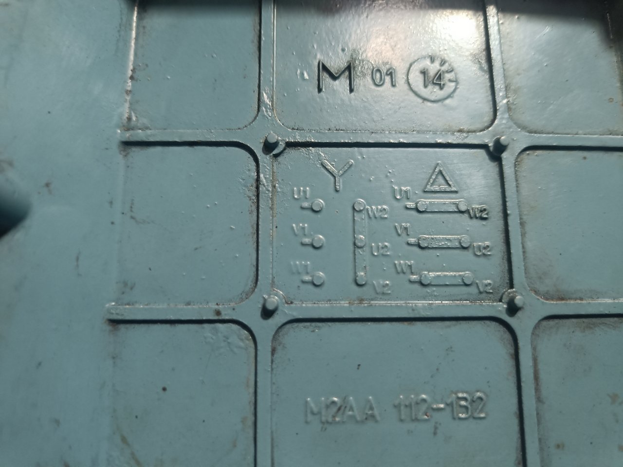
Then, I check if the motor coil connection is good. First, I took off three copper bars. Then, I set the multimeter to Ohms. Then I held the two knobs of the multimeter to U1 and W2 and got no readings on the meter.
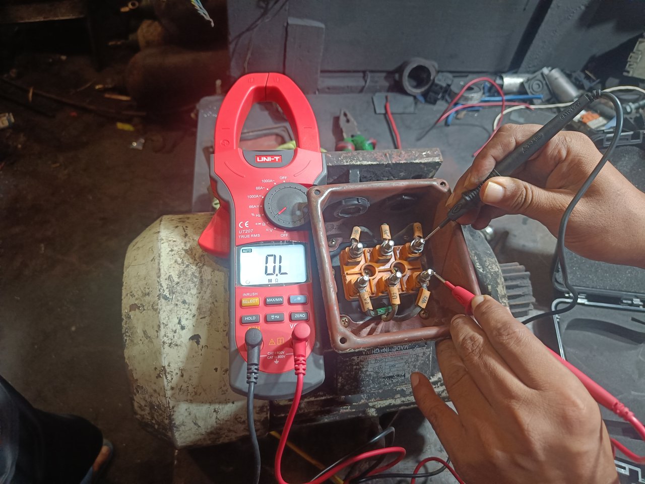
U1 & W2
Then, I hold the knob of the multimeter to both V1 and U2. In this case, too, no value was found in the multimeter.
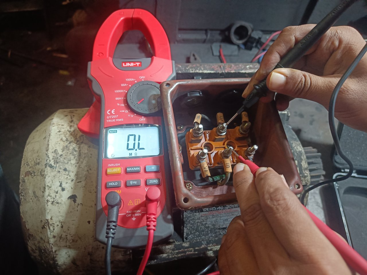
V1 & U2
Then, I hold the knob of the multimeter to both the W1 and V2 terminals. Still no value on the multimeter. According to these three test reports I can say that the motor coil connection is good. If the multimeter shows a value in one of the three test reports, the motor coil connection is incorrect.
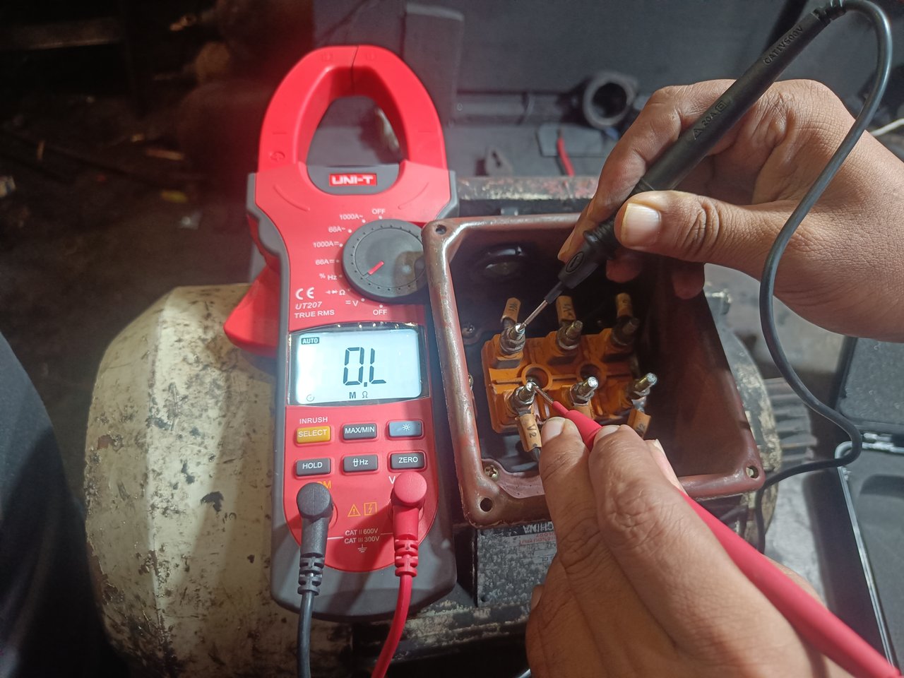
W1 & V2
Then, I hold the knob of the multimeter to the W1 and W2 terminals. Then, I got a result on the multimeter.
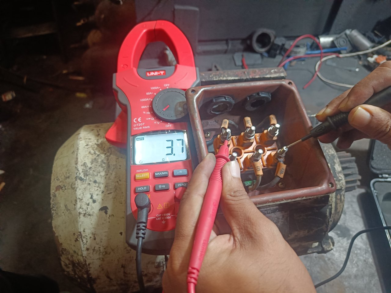
W1 & W2
Then I hold the knob of the multimeter to both the V1 and V2 ends and still get a result on the multimeter, which is shown in the picture below.
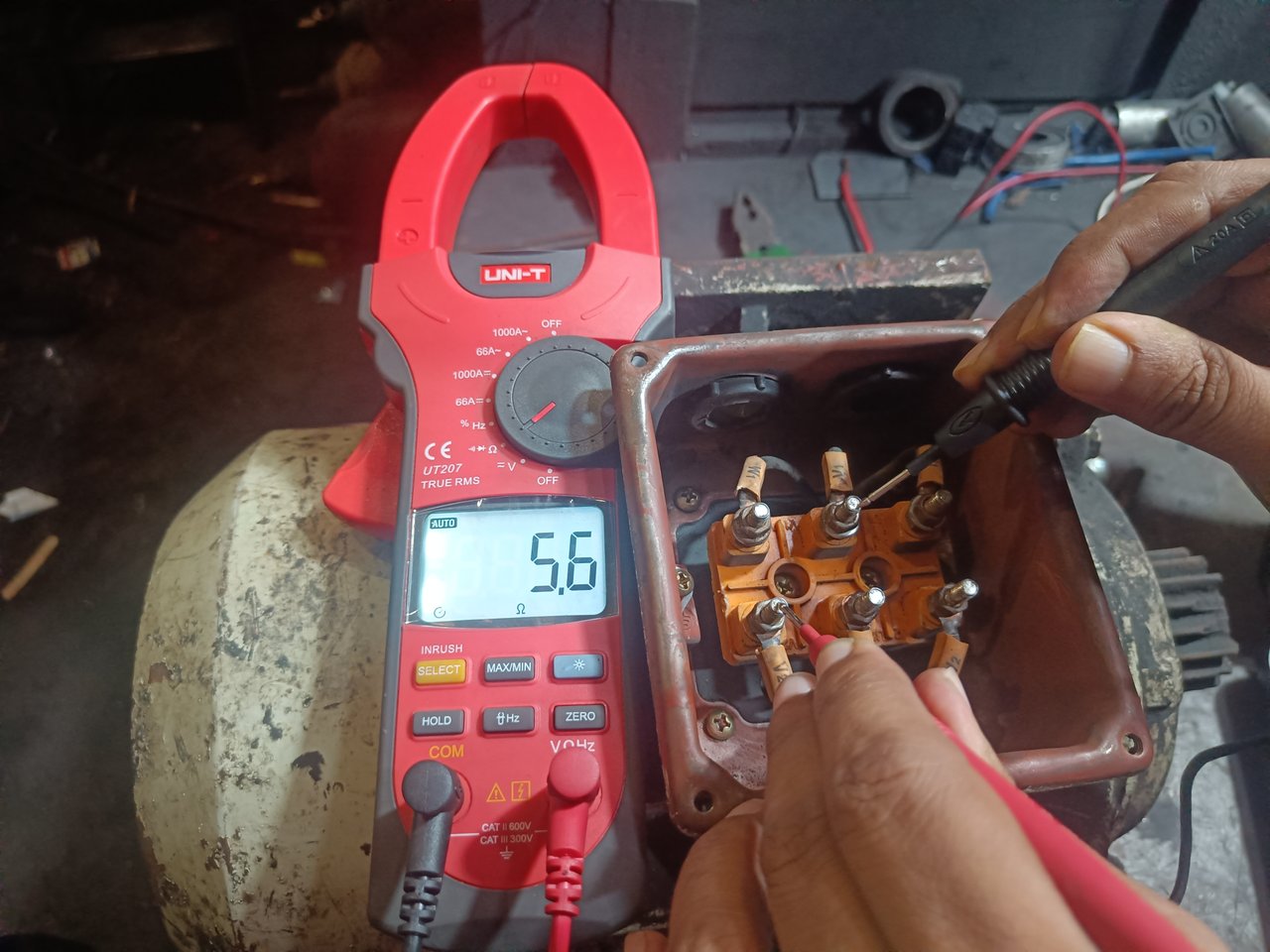
V1 & V2
Then, I hold the knob of the multimeter to the U1 and U2 terminals. I still got a result on the multimeter, shown in the picture below. Each of these three test reports gives almost the same value. According to these three test reports I can say the motor is good. If I hadn't gotten the results on the multimeter in a report, I would have assumed the motor was bad.
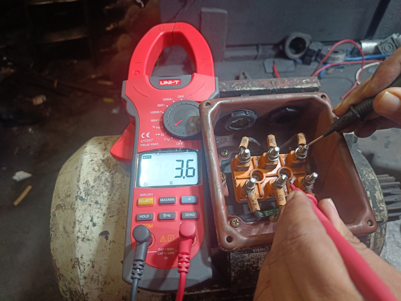
U1 & U2
Finally, I connect three copper bars, U1 & W2, V1 & U2, and W1 & V2 ends. Then, I provide a power supply through three red, yellow, and blue wires from U1, V1, and W1 ends. Thus, a three-phase induction-type motor is delta-connected.
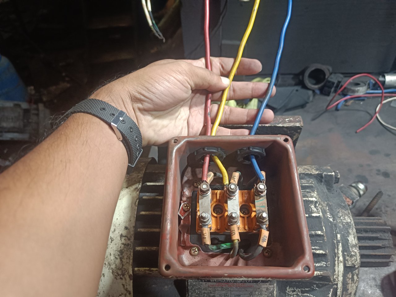
Hopefully, in the above process, you will also be able to delta-connect a three-phase induction-type motor and check its pros and cons. I hope everyone will benefit from reading my writing. Next week, I will write about another industrial electrical topic.


