Steemit friends,
How are you all? I hope you are all well by God's grace. I am also fine by the grace of God. Today, I will write about my Electrical Learning Part - 05. Today, I will show the generation of DC electricity from AC electricity. I hope everyone will like and benefit from my writing.
.png)
Design By Canva
Let us first learn about DC electricity. DC electricity is basically electricity obtained from batteries. DC electricity is a different voltage. The DC power obtained from the battery is 12, 24, and 110 volts. Still, we can increase or decrease the voltage by using different devices as per requirement.

Me with my hand-drawn picture
Industrial DC power is a little different. Industrial DC power is 220 volts and 415 volts. DC power filtering is done industrially using various techniques. Today, I will discuss about DC electricity.
In the diagram, AC and DC currents are shown. AC Electricity Figure A shows AC electricity with one positive half-cycle and one negative half-cycle. On the other hand, DC electricity is direct or parallel electricity. There is no cycle on DC electricity. Below is shown the output with AC power input through an I diode.
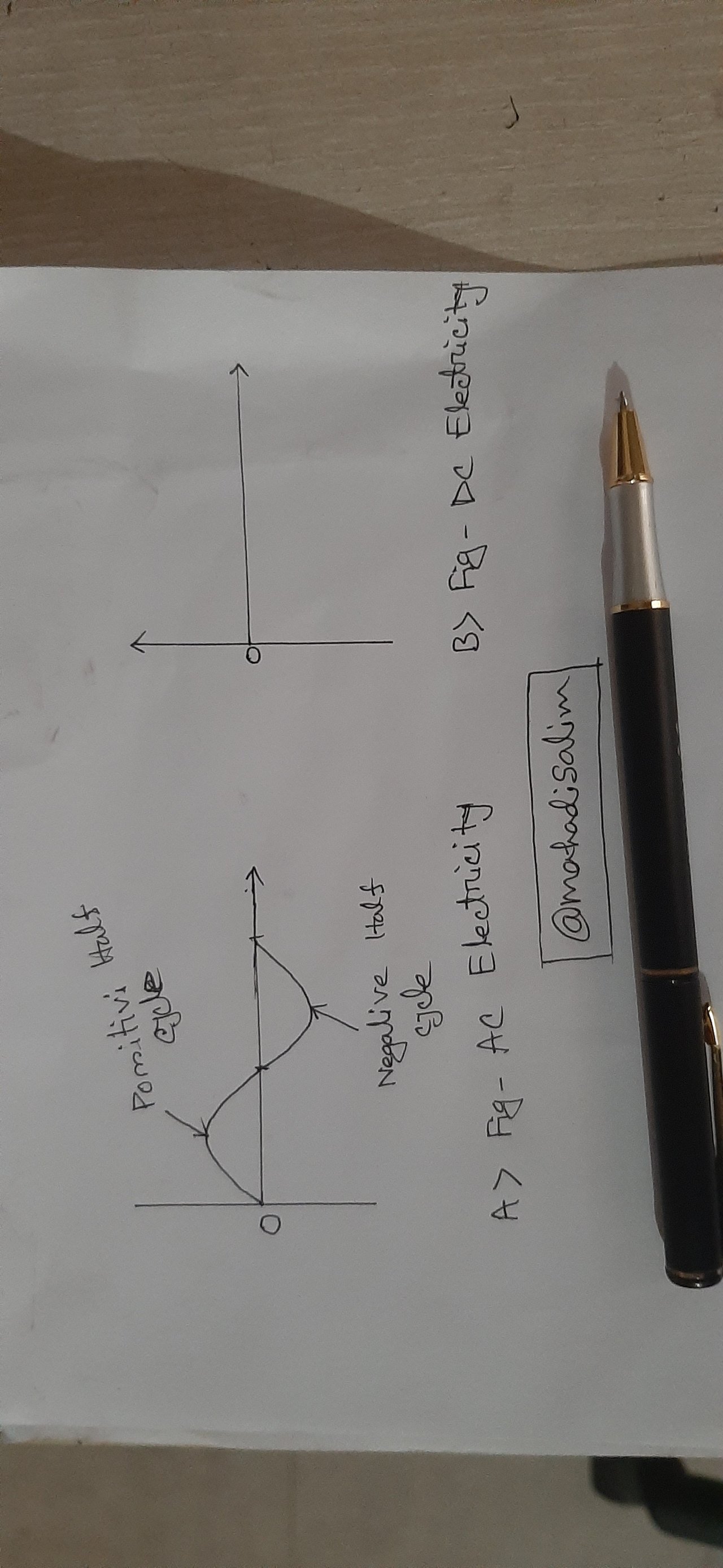
AC & DC Electricity Diagram
In Figure C, first, I made the circuit with a diode. An AC power supply is provided at the input of the circuit. We know that AC electricity has two half cycles, positive and negative. First, I will apply it to the positive half-cycle diode. Then, the diode will turn on. A current will then be obtained at the output. It is shown in Fig.
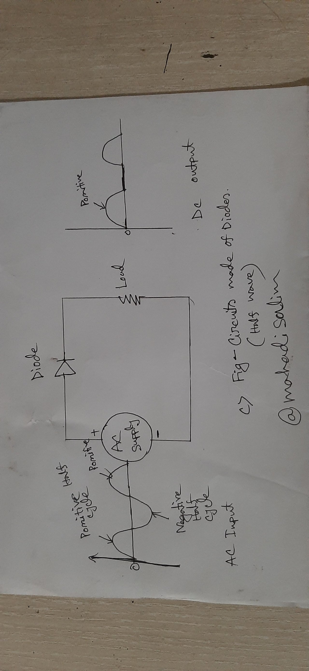
Half-Wave Rectifier Diode Circuit Diagram
Again, when applying a negative half cycle from the input AC power, the diode will be off because the diode turns on in the positive half cycle. Then, no current is available at the output. It is shown in Fig.
As seen in Figure D, a full web circuit diagram is shown. Two diodes are used in the circuit. A first positive half cycle of AC power is applied to diode-01, then diode-01 is forward biased, and diode-01 is on, then diode-02 is off. A half cycle is obtained at the output through diode-01, which is seen in the figure.
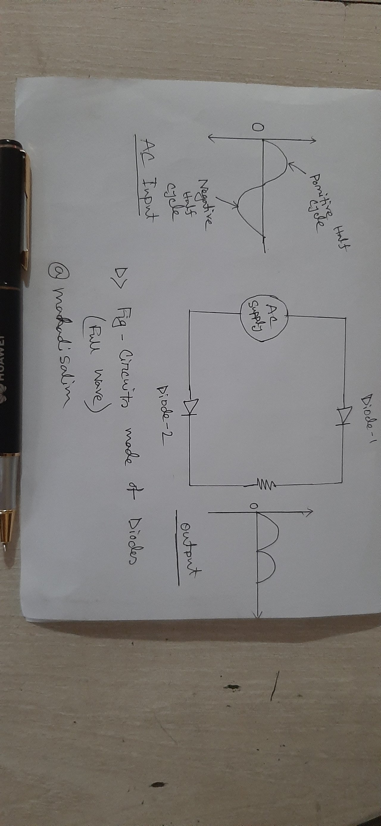
Full-Wave Rectifier Circuit Diagram
Again, when AC power is applied for the next half cycle, diode-02 is forward-biased on, and diode-01 is reverse-biased off. A current is then obtained at the output through diode-02. This is shown in Fig. Thus, a DC current is obtained at the output.
There are three diodes in the picture. The diode is formed by the P and N junction. I have shown the structural structure of the diode in the figure. Electronics can do a lot of things with diodes. There are different types of diodes. I will make a post entirely on diodes.
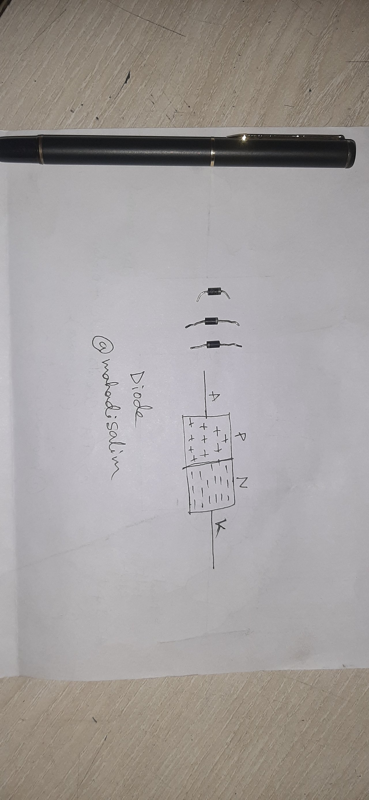
Diode & Diode Structural Diagram
I have used less engineering language in circuits so everyone can understand easily. Many of our teachers used to explain circuits in a very difficult way. Back then, many of us found the circuit to be difficult.
I can write a lot about half-web and full-web circuits. But I have written in short form for easy understanding of all. In the next post, I will write about DC power in the industrial sector.