As we all know, here would be much of electronics practical and if you are serious, you would be able to do all these things by yourself, this is our aim. The community is for learning electronics. You are always free to ask any of the professor questions base on what they teach.
Today, I thought of building one simple circuit that I use to build back then in the University. I would be doing this weekly when I have the chance.
Follow along as we might likely use this circuit much later in the academy assignments.
I mentioned buying some components few days ago..., one of the components I bought was the 555 timer.
I would be building a circuit with 555 timer Integrated circuit (IC). This IC can be used to design many other circuits for different applications. It can be used for pulse generation, Oscillation, delay and for timer circuits.
This IC working principle is vast and I can't cover all of it on this one piece, so
i'll recommend that you read it's datasheet. Hopefully, in the future, I'll feature differentICs and their features.
Infact, back then I have used it to design a traffic light...don't worry, I'll teach you how to do that much later.
It is popularly known for it's astable, monostable and bistable circuits of which I would show you samples of most of them.
For today, I would focus on astable mode circuit using 555 timer IC. That would be just a simple LED blinking at a certain frequency.
Note that to understand how an IC like this works, you need to study it's datasheet, that way, you'll be able to know the function of each pin as it would be illustrated on the sheet.
All ICs in the world has it's own datasheet. So it's best to read a datasheet of any IC you intend using so that you can understand it's working principle.
Components for this circuit
555 Timer IC
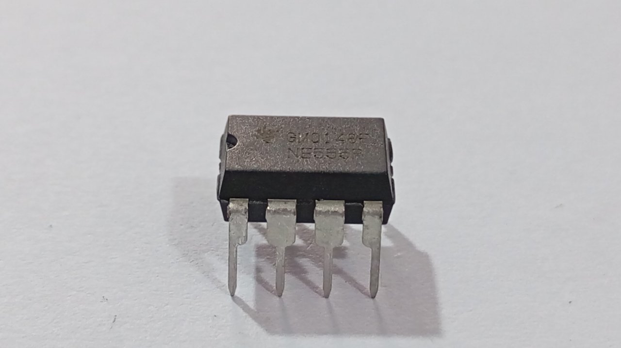
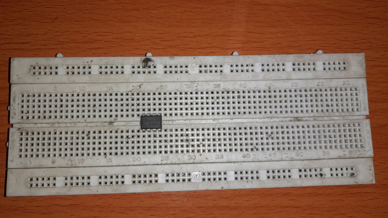
The above is the real picture of the 555 timer IC.
And below contain what we have in it's datasheep.
It is good to note that ICs are always placed upward pointing north follow the notch as I indicated below.
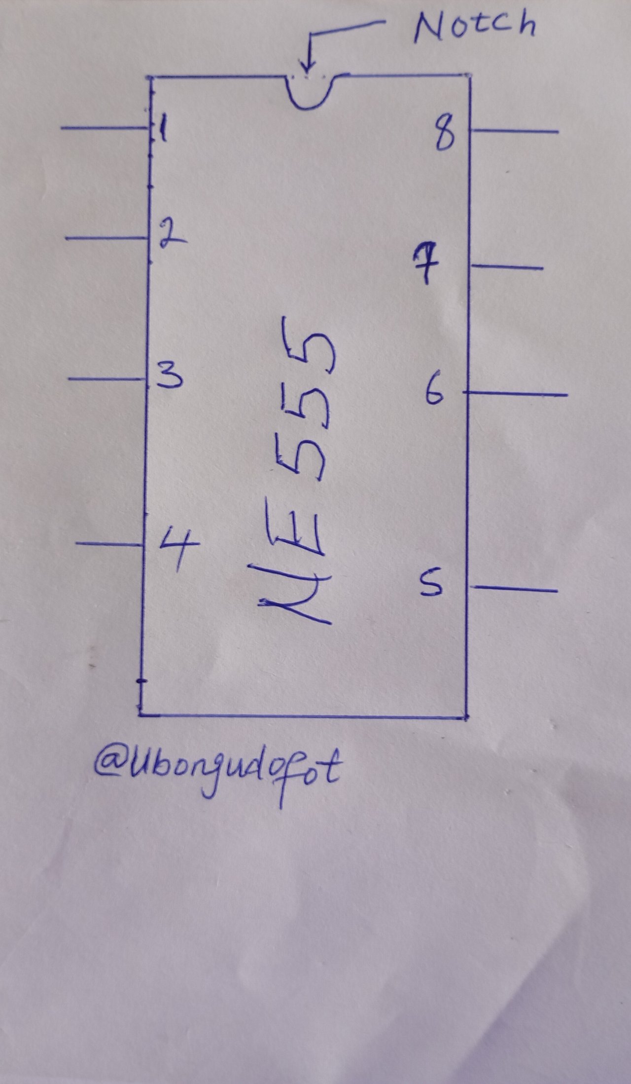
Ever wonder what each of those pins role is ? Check it out below. It is good to store this in your brains.
| Pin no. | Function |
|---|---|
| 1 | Ground |
| 2 | Trigger |
| 3 | Output |
| 4 | Reset |
| 5 | Control Voltage |
| 6 | Threshold |
| 7 | Discharge |
| 8 | Vcc |
Another component we would in this project is LED
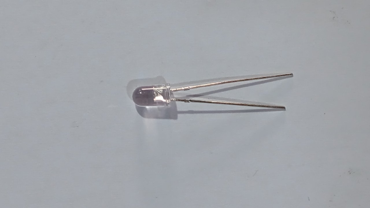
LED is a short form of "light emitting diode". This is actually a diode, but this diode comes with light, the light activate once the current comes in. The longer pin is the **anode(+), while the short leg is the cathode (-)
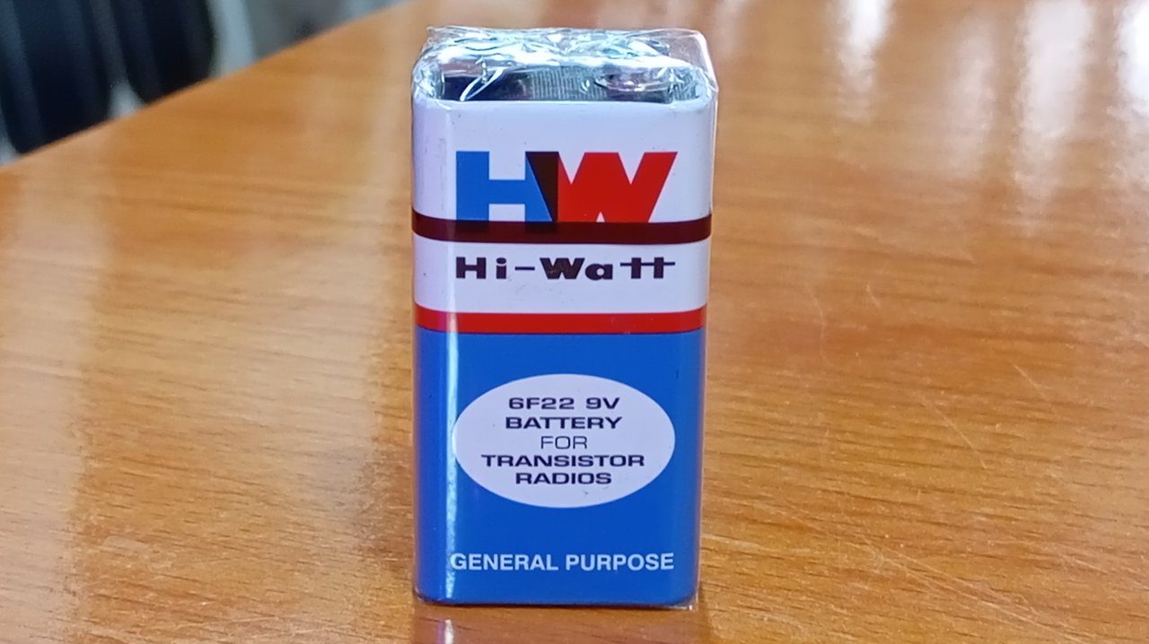
Our battery source would be 9V battery. As we cam see below
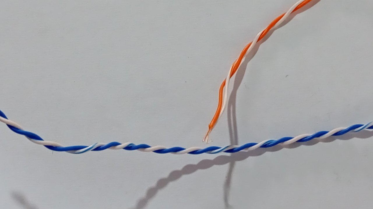
Next would be jumper wire which would be used for connections. Check it out below:
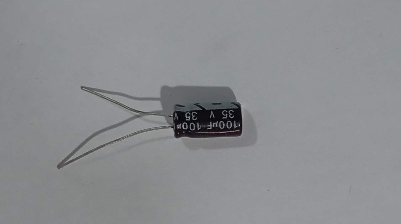
Then a capacitor. I would use 100μF by 35V. Note that the longer leg is the positive(+) while the shorter leg is the negative (-).
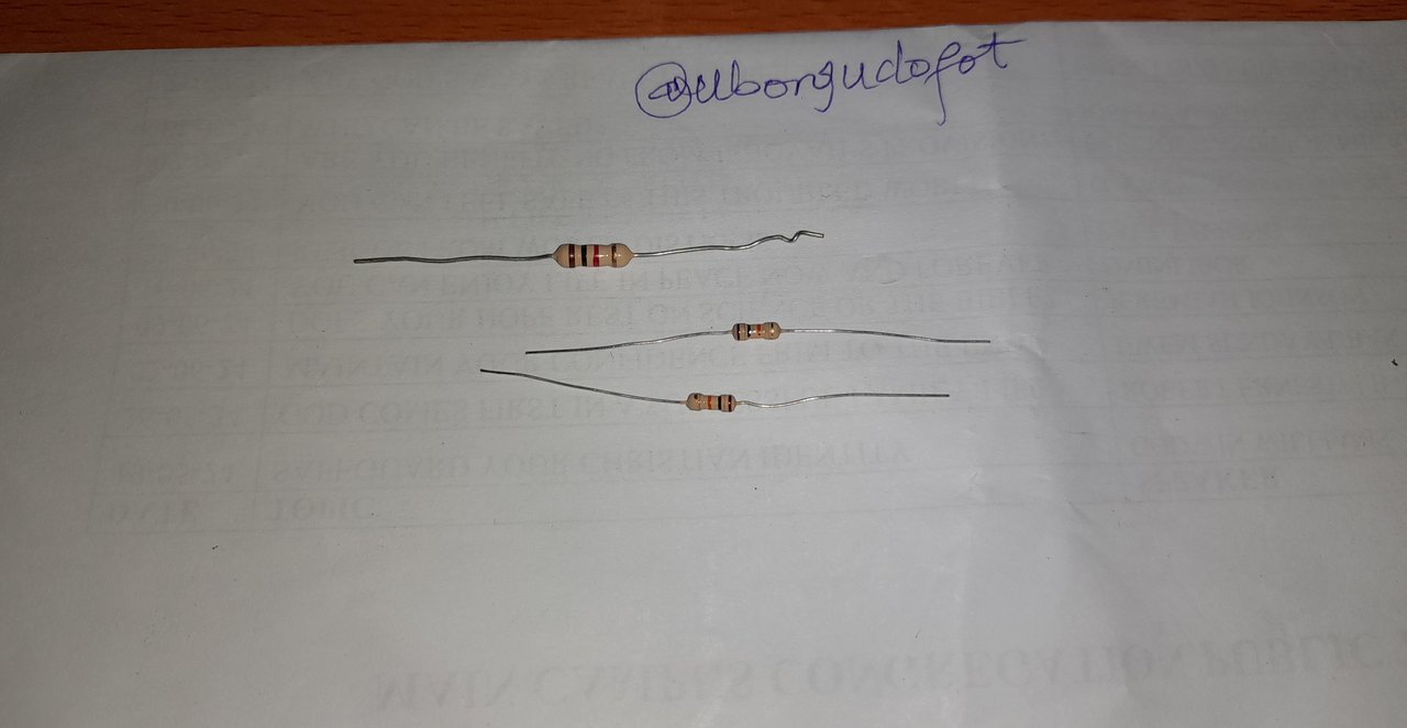
I used 3 resistors , which are 2 pieces of 10,000 ohms and 1 piece of 1000 ohms.
I would use a breadboard for this project. Breadboard are use for circuit testing or prototype. You can use it as many times as possible. What if I tell you that this the first breadboad I bought when I started learning electronics over 12 years ago in the university...?😊... Alright, now you got it!
I have ordered for two new ones for larger projects.
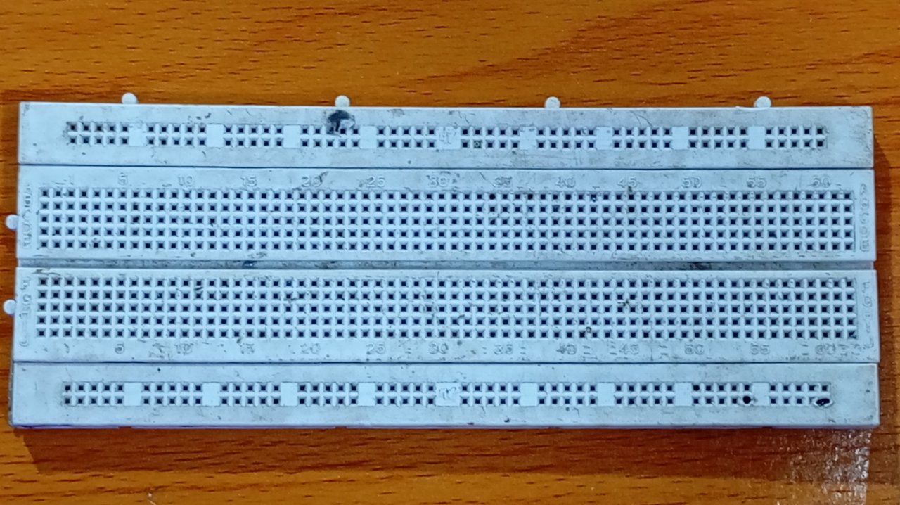
It is worth noting that breadboard is just a composition of wires arranged horizontally and vertically for easy connections of components, so you need to be careful where you place your components .
Let's get to work
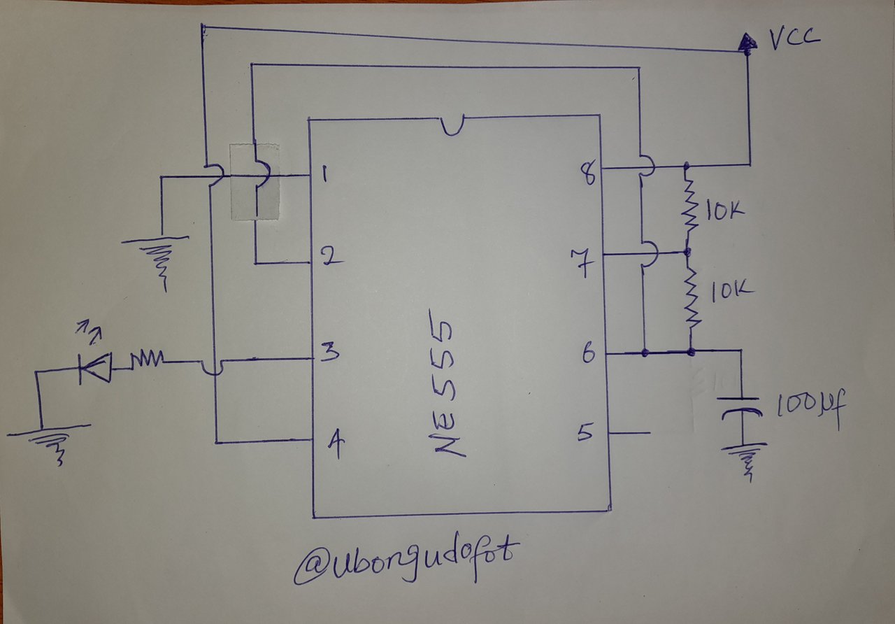
Here is the circuit I would be building below, it's an an astable multivibrator. Here the circuit will oscillates between two states and continously producing a square wave output. The LED would be blinking continuously- ON and OFF.
First thing would be to place your IC on thr breadboard, note how I placed it. This was the first thing I did.
Next would be to connect my source terminals...as seen below..
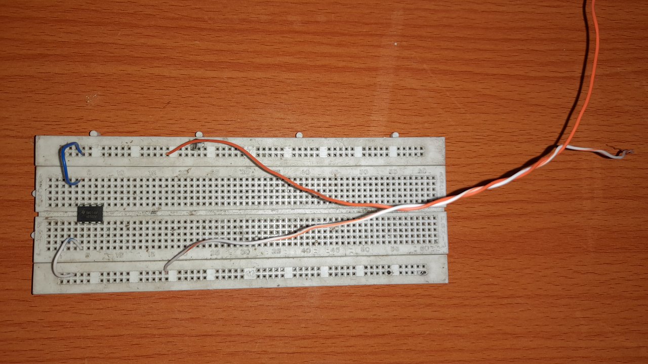
Fux other components as it is connected on the circuit diagram above.
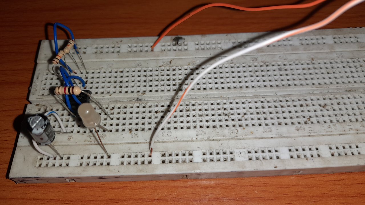
And after the whole of that, look at the result below...👇👇
This is where I would stop for today. I would use this circuit to develop many other things. And most most likely, we would use this circuit in one of our classes, this could be a good time to study it..., ask questions etc.

 |  |
|---|---|