
Welcome to Part 2 of the LED Chaser project, also known as "Night Rider". In Part 1, I demonstrated how to build the circuit itself, this is the continuation or one of the application of this circuit.
Did you miss it? Please visit Part 1 to read more about its background.
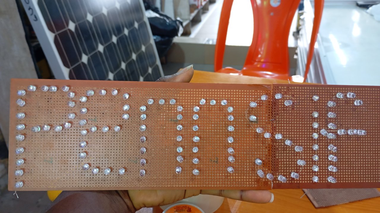
In part 2 of this project, I will design someone's name, maybe one of my witness. Can you guess..?
In my previous tutorial, I mentioned that I would build the screen for this circuit in Part 2 and also hinted that I might name it after one of my top witnesses. That would @pennsif 😀.
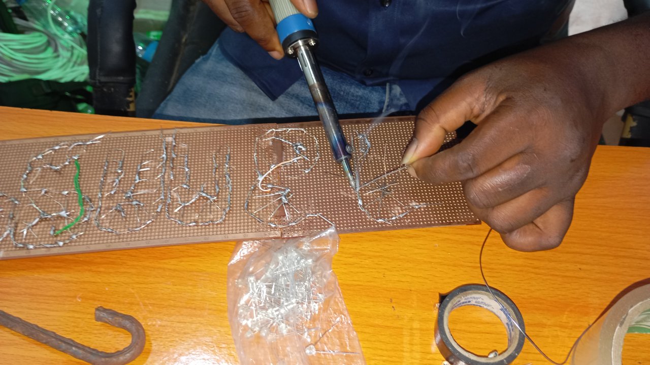
So, here I am, keeping my promise. Today's tutorial will focus mainly on soldering the screen and connecting it to the main circuit, which involves soldering the LEDs to form the screen.
Circuit of the week
LED chaser circuit (or night rider) Part 2
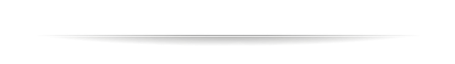
Components I used:
| Component | Quantity | Price (Naira) | Steem |
|---|---|---|---|
| LEDs | 112 | 6,720 | 27 |
| Vero board | 2 | 600 | 2.5 |
| 1kΩ resistors | 2 | 40 | 0.2 |
| Iron gum | 1 | 500 | 2 |
| Jumper wire | 1 yard | 200 | 0.79 |
| - | - | 8,060 | 32.49 |
Approximately, 35 STEEM can build this screen with soldering lead inclusive. The prices above was based on the current rate as at the time I was preparing this post, but it actually cost about 35 STEEM getting those few components as at the time I bought them.
Tools I used:
- Soldering iron
- Soldering lead
Building process
Step 1: Selection of the LEDs by colors and per letters.
While building this screen, I used various colors just to beautify it. And as for the letters, the table below captures the number of LEDs I used per letter:
| Letter | No. of LEDs |
|---|---|
| P | 20 |
| e | 19 |
| n | 17 |
| n | 17 |
| s | 16 |
| i | 8 |
| f | 15 |
I also joined two veroboards together with iron gum since the characters I would be using are a little bit longer than the normal vero board size.
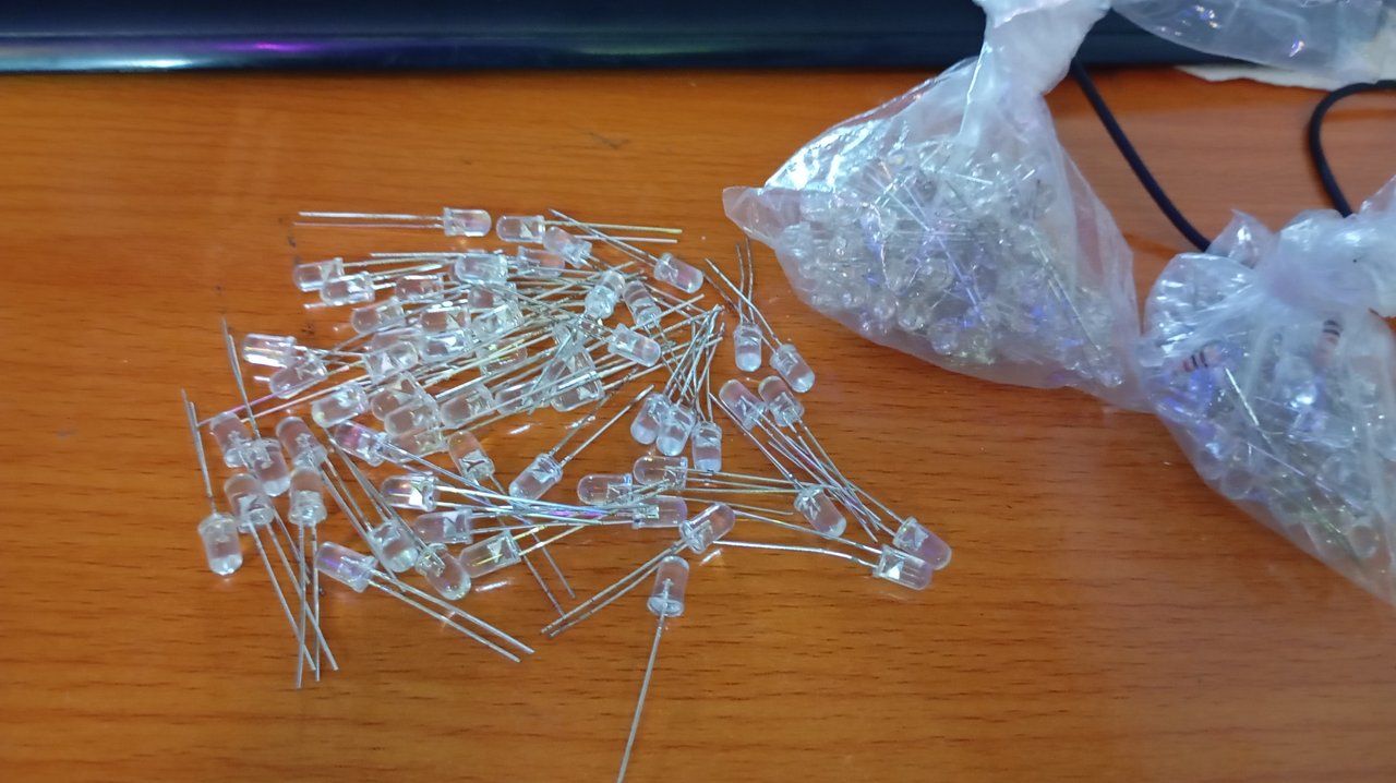
Step 2: Fixing of LEDs on Veroboard.
A
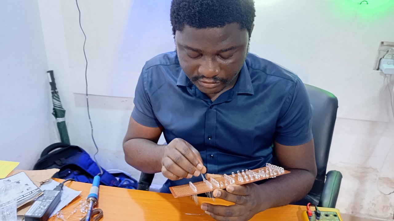
At this point, I formed each of the letters on the board using the LEDs. I soldered each letter separately.
B
C
D
E
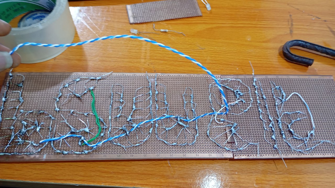
The process is simple. All the anodes of each letter are soldered together, while all the cathodes are soldered together separately as well. Note that at this point, you can first write the letter you want to form on the board and then place the LEDs following the letter drawing.
Step 3: Connecting the screen to the main circuit. I joined the screen to the main circuit which I already built in part 1. Note that all grounds are joint together, whereas, the cathode of each letters are connected to the outputs of CD 4017 according to their sequence.
Output
Day time
Night
And now, the circuit is completed! It cost 75 STEEM to build this circuit from the scratch (part 1 to part 2) to this point. So if you are planning of building this, you should have that budget or above.
It took me roughly two days to build this screen. This was because I had a very busy schedule otherwise I could finish it in one day.
Things to avoid
- Avoid placing the soldering iron on the LEDs for a long time, otherwise, they will get burnt. Generally, it is not advisable to place a soldering iron on any electronic components for an extended period.
Come next week for another interesting electronics circuit.
If you will like to build this, I can guide you from the scratch, just contact me. If you have any question, just ask on the comment section. Let's catch some fun!
@manuelhooks, @arnoldog25, @lusciouslucy ...this could be interesting to try..
 |  |
|---|---|