"Tried you to harness the wind to make it work for yourself Because wind power! -! Is one of the cheapest and most readily available I do not propose to build windmills, as it did in the old days, or a complex modern windmill But to build a wind turbine to generate electricity. albeit small, low-power, I think, be able to each family living in the countryside, each school.
Energy produced wind turbines, enough to turn on the pump for watering the garden or the garden, to illuminate the home or classroom. And if at least every fifth house will run its free mini - wind power plant, imagine how many kilowatt-hours saved will form the "energy piggy bank" of our country! "
Together with his father Sergei is going this summer to build a wind farm near the house. In a letter he sent sketches of their future installation. We showed them the engineer Vyacheslav Nikolaevich Shumeeva, he carefully studied the sketches, finalized and now offers them to readers.
Sergei Courneuve using known even in ancient times, wind turbine scheme with self-rotating drum.
The device consists of two halves of a hollow cylinder, which, after its cutting parted outward from the common axis (see. Fig. 1A). The resulting body has a pronounced asymmetry of the wind. The incident across the axis of the flow of air as it slid from the convex side of a half-cylinder. But the other, facing the wind kind of pocket, has a significant resistance. The drum is turned, half-cylinders swapped faster and faster, and the spinner so quickly untwisted.
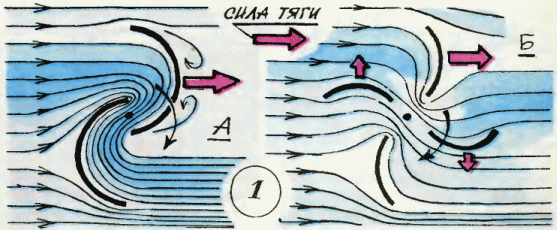
That this principle, perhaps without knowing it, and took as a basis for its future wind power plant Sergei Courneuve.
This scheme compares favorably with wind turbine propeller spinner. Firstly, it does not require the production of high precision and provides a wide range of materials used. Secondly, it is compact.
Judge for yourself. power generator, driven by the drum with a diameter of about one meter, will be the same as when using a three-bladed propeller with a diameter of 2.5 m! And if the propeller water meter must be installed on the high bar or on the roof of the house (this requires a safety), then the chopper drum can be placed directly on the ground, under a canopy. We have the drum and has a number of advantages: high torque at low engine speeds (mean, you can do completely without any gear or use a simple one-step), the absence of brush tokosemnogo mechanism.
Serge offers two-blade reel, we also recommend increasing the number of blades of up to four (Fig. 1B). Traction characteristics of such a facility will significantly improve.
Let's start with the manufacture of drum (Fig. 2). The blades can be made of plywood, roofing iron, duralumin sheet or a plastic sheet of suitable size. In any case, try to avoid overly thick workpieces - the rotor must be easy. This will reduce friction in the bearings, and hence the drum will be easier to unwind wind.
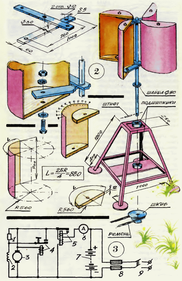
Figure 3:
1 - resistor;
2 - generator stator winding;
3 - the generator rotor;
4 - Voltage Regulator;
5 - reverse current relay;
6 - ammeter;
7 - Battery;
8 - fuse;
9 - the switch.
If you take advantage of roofing iron, the vertical edges of the blades strengthen by placing flanging a metal rod with a diameter of 5-6 mm. If you decide to make a pinwheel parts of plywood (its thickness should be 5-6 mm), do not forget to impregnate the preform hot linseed oil. The cheeks of the drum can be made of wood, plastic or light metal. Putting the drum, do not forget to miss the mark places of thick oil paint joints.
Crossings connecting the individual blades of the rotor, it is better to cook or riveted steel bands section 5x60 mm. And timber can be used: workpiece thickness is not less than 25 mm, width - 80 mm.
Axis turntable for the easiest way to make the two-meter length of steel pipe with an external diameter of about 30 mm. Before you pick up the workpiece axis, locate the two ball bearing, preferably new. Having agreed on the size of the pipes and bearings, you save yourself a lot of work on the pipe fitting to the bearing inner race. The steel rotor are welded to the cross axis mounted wooden epoxy and steel pins 5- 6mm diameter, while passing through each crossbar and the pipe. The blades mount bolt M12. Carefully check the distance from the blade to the axis, they must be the same - 140-150 mm. Gathering drum back cover of thick oil paint joints parts.
The main element of the installation is ready, it remains to make a base frame, welded or riveted to it from the metal bracket (good and a wooden version). On the base frame finished install bearings. Make sure that there is no misalignment, otherwise the rotor will not rotate easily. All items installed, double coat of oil paint, on the lower end of the shaft fix a set of pulleys of different diameters. Thrown over a pulley belt turntables connected to a generator of electric current, such as automotive. Built sample of wind power plant with a wind speed of 9-10 m / s can provide the power transmitted to the generator of 800 watts.
Well, if there is windless weather or the wind is too weak to put the necessary energy? Interruptions in electricity generation will not be, if we use the energy storage - the battery. Wind is - start up electricity directly to the consumer, there is no wind - wind turbines turn charged by batteries. In Figure 3, we have shown a schematic electrical circuit device such wind turbines.
If the wind turbine will be used for watering the garden or the garden, it should be mounted directly above the source of water.
Now the task. Think of guys like to accommodate wind turbines, of which we spoke, for geologists, climbers, mobile repair, and construction crews, to the shepherds on distant pastures.
Wind turbine for a wind turbine
The proposed design allows the wind turbine to increase vetroeffektivnost almost 3.2 times in comparison with the classic and bring it to a value of 0.65-0.75.
INVENTION
Russian Federation Patent RU2283968
name of the inventor: Stanislav Lisnyak Afanasievich (RU); Vyalykh Sergey (RU)
The name of the patentee: Lisnyak Afanasievich Stanislav (RU); Vyalykh Sergey
Address for correspondence: 690001, Vladivostok, st. Pushkinskaya, 37, FESTU, patent department, MI Zvonareva
Starting date of the patent: 2005.02.21
Know-how development, namely the author, this invention relates to wind power and can be used to convert wind energy into mechanical motion of the rotation shaft of the windmill, to which can be attached a variety of mechanical devices, or mechanical energy converters. The technical result consists in simplifying wind turbine design, reducing its weight and size characteristics, increasing the energy efficiency of the wind, is provided by the fact that the wind turbine comprising a wind wheel with vertical axis of rotation, provided with at least three vetrovosprinimayuschimi elements fastened with radial traverses enshrined on the vertical axis of rotation perpendicular to it, with the outer ends of the traverse are simply supported on the annular support, moreover, wind wheel mounted to interaction with the electric power generator according to the invention, each vetrovosprinimayuschy element is designed as a slotted wing comprising at least two parallel blades, the profile of the cross section which imparted a crescent shape convex in the direction of rotation of the propeller and the concave side vetrovosprinimayuschih surfaces, the width and length of the blades slotted wing increases from its surface that receives the wind is not less than 5% of the size of the adjacent lower, the cross-section of the largest blade each slotted wing formed into drop-like shape, for which the radius of curvature of its profile the central part of the convex surface is made smaller than the other blade wing gap.
DESCRIPTION OF THE INVENTION
Know-how development, namely the author, this invention relates to devices for converting wind energy into mechanical motion of the rotation shaft of the windmill, to which can be attached a variety of mechanical devices, or mechanical energy converters.
Known wind turbine in which the central region of the wind flow acts directly on the multiblade rotor, and the right and left of the flow set movable flap along the perimeter outside the rotor (left to open the flow movement, and the right side cover), these flaps are also used as guiding apparatus wind flow direction of the rotor (see. RF patent №2074980).
The disadvantage of this solution - using wind sector angle less than 120 °, but significantly increased the size of the entire device structure is complicated and even in comparison with the wind turbine blade.
Known wind turbine configured as an axial turbine nozzle assembly comprising an electric generator and, a front, central, and additional outer shell. These membranes produce between adjacent surfaces of the three channels, each of which is a Laval nozzle (see. RF patent №2124142).
According to the author, this design provides a high efficiency of the use of wind, which is debatable, since the diameter of the outer shell by more than an order of magnitude larger than the diameter of the turbine itself, mean aerodynamic torque envelope is nearly a thousand times more resistance to the turbine. the author's claim that the investments by 1 kW of power of the wind turbine will be no more than 0.25 investment for a classic windmill does not hold water (now the world capital of 1 kW wind turbines are on average $ 1,500-2,000).
Also known wind turbine comprising a wind wheel with vertical axis, provided with at least three vetrovosprinimayuschimi elements bonded with radial cross-members fixed to the vertical rotation axis perpendicular thereto, wherein the outer ends of the traverse are simply supported on the annular support, moreover, wind wheel mounted to the interaction an electric power generator (see. US Pat. Russian Federation for z-ke №2002130128 from 10.11.2002 "Wind Turbine", the decision to grant a patent on 08.01.2004, the).
The disadvantage of this solution - bulkiness and relatively little use of the wind sector, in addition, to ensure the safety of the design manual, which has a developed area vetrovosprinimayuschih elements, it is equipped with devices to change their sail area.
The problem to be solved by the claimed technical solution - to simplify the design of a wind turbine, reducing its weight and size characteristics, increasing its utilization of wind energy.
The technical result obtained in the solution of the problem, reflected in the fact that if the wind regardless of its direction, its vetrovosprinimayuschih elements from 0 to 180 ° wind direction there are aerodynamic forces that cause to rotate the motor shaft, since the surface vetrovosprinimayuschih elements, moving into the wind, have a lower aerodynamic drag. This provides an increase in the use of wind to 175 ° sector angle of rotation of the shaft, i.e. 1.6 times higher than the classical (at angles of 2,5 ° to 177,5 ° from the direction of the wind). In addition, the performance of the blade on the wing slot type NE Zhukovsky improves aerodynamic forces on the blades in the 1.7-2 times compared with single - normal blade.
To solve the windmill tasks comprising wind wheel with vertical axis, provided with at least three vetrovosprinimayuschimi elements bonded with radial cross-members fixed to the vertical rotation axis perpendicular thereto, wherein the outer ends of the traverse are simply supported on the annular support, moreover, wind wheel set with to cooperate with the electric power generator is characterized in that each vetrovosprinimayuschy element is designed as a slotted wing comprising at least two parallel blades, the profile cross-section which imparts a crescent shape convex in the direction of rotation of the propeller and the concave side vetrovosprinimayuschih surfaces, the width, and length of the blades slit wing increases from its surface that receives the wind is not less than 5% of the size of the adjacent lower, the cross-section of most blades each slotted wing formed into drop-like shape for which the radius of curvature of the profile of the central part of its convex surface is made smaller than that other slit blade wing. Moreover, forming the lower surface of vetrovosprinimayuschey slotted wing blade radial and perpendicular to the vertical axis of rotation.
Comparative analysis of the features of the claimed solution to the signs of the prototype and analogues indicates compliance of the claimed solution to the criterion "novelty".
Signs of the characterizing part of the formula provide a solution to the following functional tasks:
Signs "vetrovosprinimayuschy each element is designed as a slotted wing comprising at least two parallel blades" will improve the aerodynamic forces on the element vetrovosprinimayuschem 1.7-2 times as compared with the conventional - single blade.
Signs of "cross-sectional profile of the blades formed into crescent shape convex in the direction of rotation of the wind wheel and concave side vetrovosprinimayuschih surfaces" provides that if the wind regardless of its direction, on vetrovosprinimayuschih elements from 0 to 180 ° wind direction there are aerodynamic forces that cause spin motor shaft, since the surface vetrovosprinimayuschih elements moving into the wind, have a lower aerodynamic drag than vetrovosprinimayuschie surface.
Sign "width and length of the slotted wing blade increases from its surface that receives the wind is not less than 5% of the size of the smallest neighboring" provides interoperability with all wind slotted wing blade.
Signs "greatest cross-section of each slotted wing blade formed into drop-like shape, which radius of curvature of the profile of the central part of its convex surface is made smaller than the other blade wing gap" allow to minimize the aerodynamic resistance of the leading edge vetrovosprinimayuschih elements.
Signs of the second paragraph of the claims define the spatial reference slotted wing blade in relation to the axis of rotation.
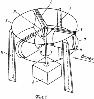
Figure 1 shows a general view of a wind turbine
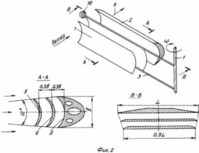
2 shows enlargement slotted wing
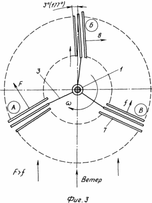
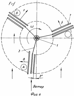
3 and 4 shows the interaction of the wind wheel with the wind at different angles of rotation of the wheel to the wind.
Wind turbine includes wind-wheel with vertical rotation axis 1, provided with at least three vetrovosprinimayuschimi elements 2, fastened with radial cross-members 3, rigidly fixed on a vertical axis of rotation 1, perpendicular to it (for large size propeller number of traverse is two, for small, you can use only one crosspiece ). The outer ends of the traverse 3 4 simply supported on an annular support 5. If necessary (for larger sizes vetrovosprinimayuschih elements), you can use two parallel support rings spaced in height one above the other, but according to our calculations, in most cases, only one. Wind wheel mounted to interaction with the electric power generator 6. Each vetrovosprinimayuschy element 2 is designed as a slotted wing comprising at least two parallel blades 7, spaced apart in the plane of rotation of the rotor from each other by 0.3 blade chord at the wing Zhukovskogo slit type N. E. Profile cross-section of the blades 7 formed into a crescent shape convex in the direction of rotation 8, the propeller and the concave side vetrovosprinimayuschih surfaces 9, wherein the width and length of the blades slotted wing increases from its concave surface that receives the wind is not less than 5% of the size of the adjacent lower . The greatest cross-section of each slotted wing blade formed into drop-like shape, which radius of curvature of the profile of the central part of its convex surface is made smaller than the other blade wing gap. In addition, the forming surface 9 vetrovosprinimayuschey least one of the blades 7 slotted wing radial and perpendicular to the vertical axis of rotation 1.
The outer ends of the traverse 10 provided with the flanged rollers which are simply supported on a support ring 5, with the possibility of rolling over it. The annular support 5 is fixed on the support mast 11 (at least three).
Wind turbine operates as follows. In the presence of wind, on vetrovosprinimayuschih elements 2, with wind directions from 0 to 180 ° there are aerodynamic forces that cause the motor to rotate the shaft (vertical axis of rotation), since the surface of the slotted wings, moving into the wind, have a lower aerodynamic drag. Thus, in the slotted core there are additional wing aerodynamic forces in accordance with the properties of the slotted wing which increase the aerodynamic forces acting on the blades in 1.7-2 times in comparison with single - conventional blade.
Interaction vetrovosprinimayuschih elements 2 with the wind presented in Figure 3, 4 at different angles of rotation of the vertical rotation axis 1.
It follows from the drawings that the blade unit is rotated from 0 ° to almost 180 ° resultant aerodynamic force is retained on vetrovosprinimayuschem element.
Increasing the number of blades in vetrovosprinimayuschih elements more than three would only reduce the efficiency of the wind turbine.
By turning vetrovosprinimayuschih elements from 0 ° to 180 ° practically saved the resultant aerodynamic force on it.
The presence of the support ring 5, reinforced by at least three support masts 11 provides almost complete discharge and traverse vertical rotation axis of the wind turbine at a wind tipping moment any force.
The rotation axis of the vertical rotation shaft 1 is transmitted to the electric power generator 6 with electricity.
Thus, the proposed design allows the wind turbine to increase vetroeffektivnost almost 3.2 times in comparison with the classic and bring it to a value of 0.65-0.75.
CLAIM
Wind turbine comprising a wind wheel with vertical axis, provided with at least three vetrovosprinimayuschimi elements bonded with radial cross-members fixed on the vertical axis perpendicular thereto, wherein the outer ends of the traverse are simply supported on the annular support, moreover, wind wheel mounted for interaction with a generator of electrical energy, characterized in that each vetrovosprinimayuschy element is designed as a slotted wing comprising at least two parallel blades, the profile cross-section which imparts a crescent shape convex in the direction of rotation of the propeller and the concave side vetrovosprinimayuschih surfaces, the width and length of the blades slotted wing increases from its surface that receives the wind is not less than 5% of the size of the adjacent lower, the cross-section of most blades each slotted wing formed into drop-like shape for which the radius of curvature of the profile of the central part of its convex surface is made smaller than the other blades slotted wing.
Wind turbine according to claim 1, characterized in that the forming of the lower surface vetrovosprinimayuschey slotted wing blade radial and perpendicular to the vertical axis of rotation.
literature:
http://poselenie.ucoz.ru/publ/http_www_youtube_com_v_exge5_c5h9y_hl_ru_ru_fs_1/6-1-0-32
http://www.ntpo.com/izobreteniya-rossiyskoy-federacii/elektroenergetika/alternativnye-istochniki-energii/vetroelektrostancii/16221-vetrodvigatel-dlya-vetryaka.html