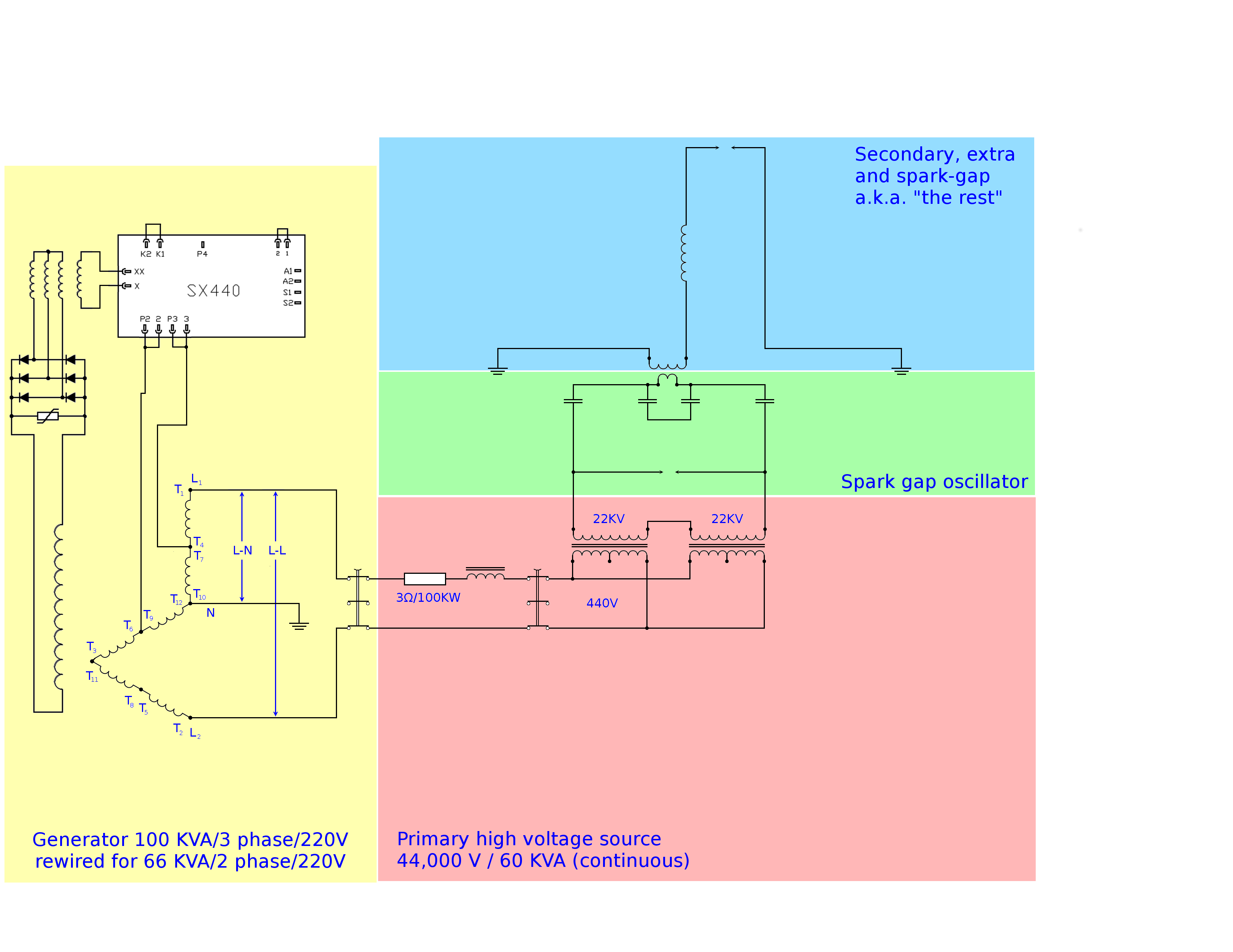
Now that we have a high frequency, high voltage source the real fun starts.
The oscillator from the previous part incorporates our primary coil so we only need to add a secondary.

The design of our secondary is very straightforward. Tesla mentions on may occasions that the wirelength of this coil needs to be ¼ wavelength and it appears as though he assumes a velocity of c (speed of light). Again this is a point that can raise many discussions, but these can easily be circumvented by designing a coil such that the velocity factor equals 1.
That way we can all agree that our pulses travel through the coil at the speed of light, which btw is evidently not true, but it is funny that this way we can still agree on this.
OK, let me elaborate a bit on this. It is simply not true that pulses are travelling from one end of the coil to the other end, it is much more like a density wave. You can also compare it to waves on the water. A wave can travel from one end of the pond to the other while not a single molecule travels all that distance.
Having that out of the way, as I said, it is very easy to design such a coil. Namely there are 2 things you need to consider; the wire length (= ¼ wave = ¼ x speed of light / frequency) and the ratio of coil diameter / coil length (= Phi = golden ratio = 1.61803…). That is all, the entire design follows from these two quantities. To be honest, you still need to choose a suitable wire diameter, but how hard is that?
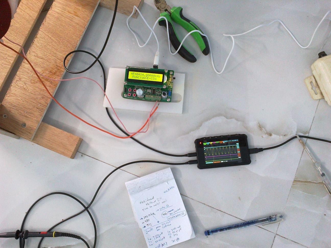
To find the frequency we simply measure the resonance frequency of the primary circuit.

Following Tesla’s design rules we need to have the same amount of metal in the primary and secondary. The primary has 10 strands of 25 mm² in 1 single turn, so that is 250 mm².
So the secondary should have the same (if it were the same metal).
The secondary has 47 turns, so we need a wire size of little over 5 mm², if both were copper.
The primary however is made of copper and the (new) secondary is made of aluminium, which is less than half the weight of copper.
The old secondary used 6 mm² copper, the new one uses 10 mm² aluminium wire.

(the old secondary)
As you can see in the first picture the lower half of the coil is extra insulated and you may wonder why, as in the top half the voltages are much higher. This is true, but there are two things that we need to consider here. First, most of the voltage is generated in the lower half of the coil and for that reason the winding-to-winding voltage is much higher in the lower half.
But then we are just thinking of a smooth resonant action. This is not at all what is happening, which brings us to the second thing we need to consider; The primary, located at the bottom end of this coil delivers a very sudden and strong pulsed force onto the charges in the lower end of the secondary. So it takes a while for the elasticity of the charges to spread this force through the entire coil.
You can compare this to having a long metal bar. If you pick it up on one end it will rise evenly. But if you drop a large weight on one end the metal can not accommodate this suddenness and it will bend.
Due to this effect the wire-to-wire voltage is much higher in the bottom end of the secondary and therefore it is this part that requires extra insulation.
Some extra details on the construction
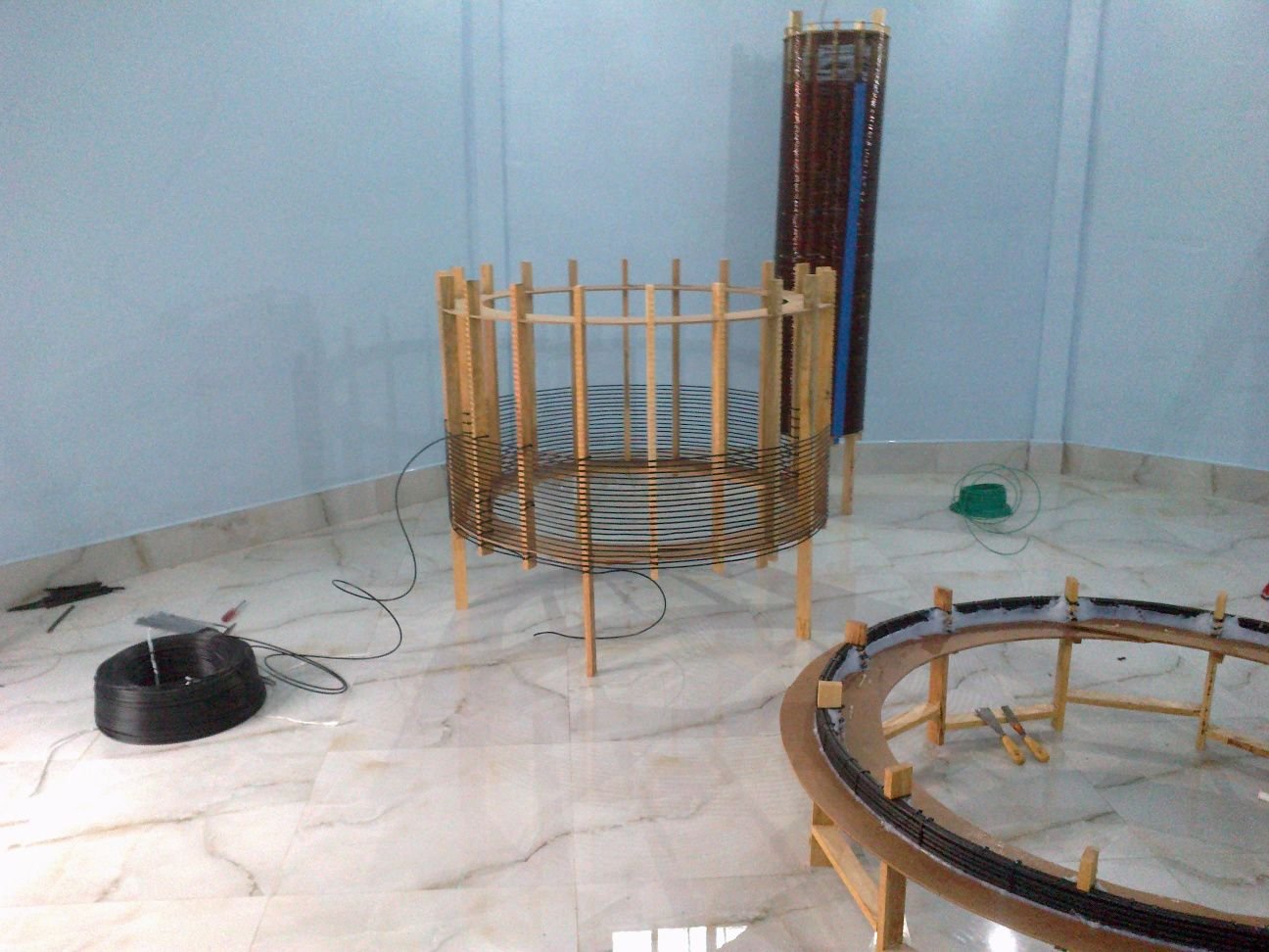
In the above picture you can see the frame. It is made of some light wood and it’s all glued together.
To hold the wires in place, I use a 15 mm PVC pipe, drill holes in it at the right distances and then cut the pipe across its length in two, giving two half-pipes with indents for holding the wire. This is glued onto the wooden frame.
Note that no metal is used as iron would affect the magnetic properties and other metals may cause sparks.
Here's a close up:
Well, next it is just a matter of silicone:
The “Extra” coil
The design of the “extra” coil is equally easy. We know the frequency and we know that we must now use half a wavelength wire. I also wanted the extra coil to have the same velocity factor which again dictates a length/width ratio (about 3.1). This ratio differs from the first because we have ½ a wavelength instead of ¼.
What makes it even more easy is that we can use 16” PVC as a frame for this coil.
This extra coil amplifies the voltage through resonance and through that we can achieve a few million volts. I have not measured its maximum nor the maximum spark length simply because it is not possible. I only have a few meters around the top.
From here we create sparks to the roof of the building. This roof is designed so that it collects its charge on the outer rim and does not spark back to the coil.
Also the roof can be electrically grounded and we can measure the current through this ground wire.
The idea is that the multi million volt spark will attract atmospheric electricity, so the current in this ground wire should be larger than the current in the ground wire of the secondary coil. Well, at least that is what we’d like to see…
Very soon.
