Hello steemians, hope you had a lovely weekend. LEDs are used in majority of electronics devices. Today, I will be writing on how to interface LEDs with a pic microcontroller. This method can also be used to interface and switch on other electronic devices such as DC motor, transistors and relays. Before diving into programming the microcontroller and the LED, let us first understand what an LED is.
what is an LED

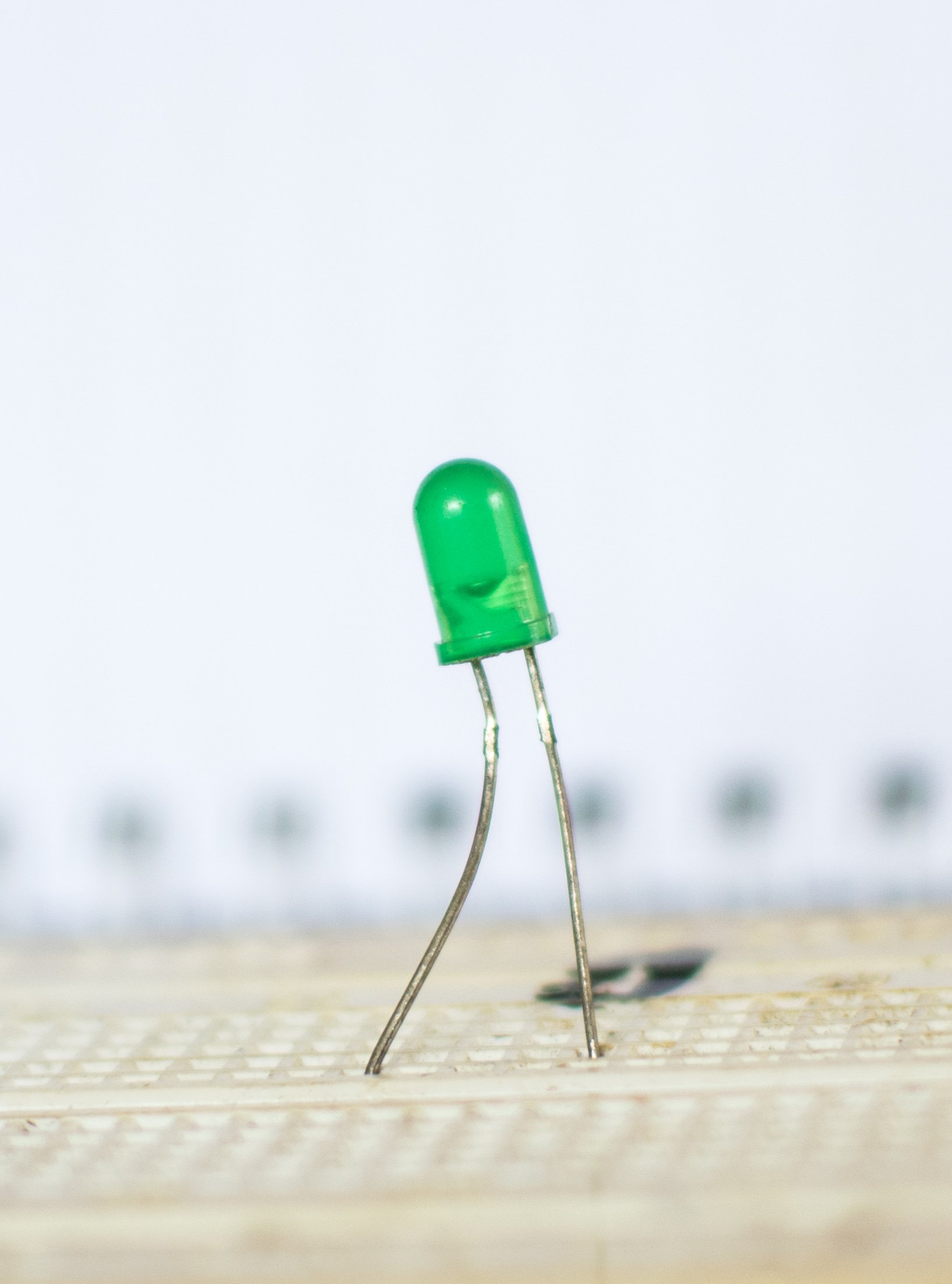
LEDs are semiconductor diodes that allows current flowing in only One Direction, but unlike other diodes, when it is forward biased it emits light hence LED means light emitting diode. It has polarity and also has two terminals. The longest terminal is the positive terminal (anode) and the shortest terminal is the negative terminal (cathode) . Applications are numerous but some of them includes; to tell or indicate the logic output state of electronic circuit and they also act has sources of light. They come in various sizes and colours.
The intensity of the light emitted by an LED, is dependent on the amount of current flowing through the terminals of the LED. If the LED is supplied with a high voltage that will cause more current to flow across it's terminals, it could burn out the LED and could also destroy the microcontroller depending on the mode in which the LED was connected to the microcontroller. To prevent this from happening, a current limiting resistor is always connected to the LED. The value of this resistor is calculated using the formula;
R= VDD - voltage drop across LED/ supplied current.
Various colours of LEDs have various voltage drop across them and maximum forward current they can handle.
For red and orange LEDs, they have a voltage drop of 2 volt and a forward current of 20mA. Yellow LEDs have a voltage drop of 2.1volt and a forward current of 20mA. Green LEDs have a voltage drop of 2.2volt and a forward current of 20mA. Infrared LEDs have a voltage drop of 1.2v and a forward current of 50mA.
Example
Calculate the value of a current limiting resistor connected to a red LED and supplied with a voltage +5v and a current of 10mA.
VDD = +5V
Voltage drop across red Led = 2v
Supplied current = 10mA.
R = 5-2/10
= 3/10
=0.3k ohms
There are two methods of interfacing LEDs to a microcontroller;
- Current sourcing mode.
- Current sinking mode.

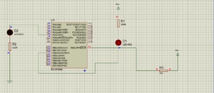
In the current sourcing mode, the anode of the LED is connected to the microcontroller. Hence the microcontroller provides the supplied voltage needed by the LED. While in the current sinking mode, the cathode of the LED, is connected to the microcontroller so as to provide it will with a logic zero. When programming the microcontroller in the current sourcing mode, the pin of the microcontroller connected to the LED is set to a logical 1 in other to turn on the LED. To turn off the led in the current sourcing mode, the pin of the microcontroller connected to the LED, is set to a logical 0. In the current sinking mode, it is the reverse. To turn on the LED in the current sinking mode, the output pin of the microcontroller connected to the anode of the microcontroller is set to a logical 0 and to turn the LED off, it is set to a logical 1.
programming the microcontroller.

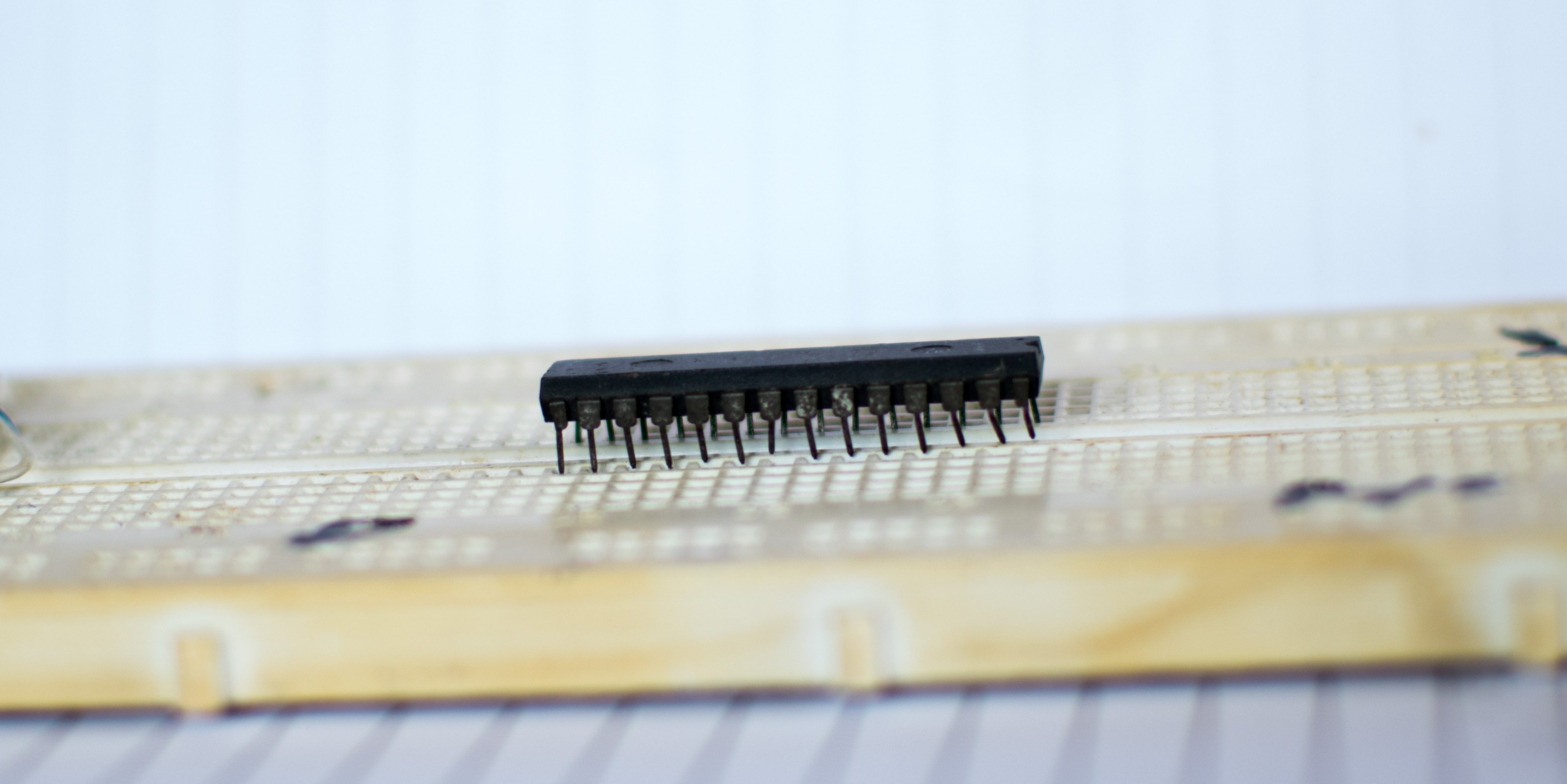
In other to demonstrate this, I am going to be using a pic18f2580 and the mikroC pro compiler.
code
void main()
{
OSCCON = 0x76; // SET INTERNAL OSCILLATOR
TRISC = 0; // SET PORTC AS OUTPUT
do
{
PORTA.RA2 = 0; // SET PORTA. RA2 AS LOGICAL 0
delay_ms(1000); //DELAY FOR 1 SEC
PORTB.RB2 = 1; //SET PORTB. RB2 TO 1
delay_ms(1000);
PORTA.RA2 = 1; // SET PORTA. RA2 TO 1
delay_ms(1000);
PORTB.RB2 = 0; //SET PORTA. RA2 TO 0
}
while (1);
}
REFERENCE
1. how to interface LEDs with pic microcontrollers
All images where taken with my Nikon D5300 DSLR camera And edited with lightroom software. The schematics was designed by me using Proteus software.
