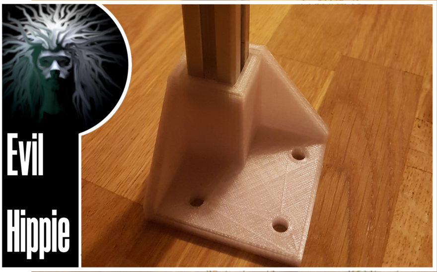
Often when 3d printing, the object that I print has to fit some already existing object. This adds another dimension to the printing since, not only do I have to work by measurement, I also have to factor in tolerances.
People who have worked with machining or modifying or repairing stuff will know what I talk about, if you haven't, stay with me and I will explain.
Say you have a hole and a bar which has to fit into the hole. There is an important difference whether the pin needs to be stuck in the hole or needs to be able to slide along in the hole.
If you do not think about tolerances, you will (Like I have done before) print a hole with a diameter of say 1.0 cm and a pin of the same diameter. This will result in a pin which wont go into the hole at all.
On your second attempt you might overcompensate and make a hole of 1.1 cm for the same pin which will result in the pin rattling in the hole. so you need to know your tolerances. My Ultimaker printer is fairly exact so usually to get a tight fit I will need to give it 0.05 mm, but this also depends on the print direction with regards to the hole.
If we zoom in on the surface of a print, the layering gives a banding effect which will increase friction significantly in the direction perpendicular to the layers. This can be fixed by sanding the surface, but thats time-consuming (and tedious)

I am currently helping out on a research project. I cant talk much about the project since it is not yet published , but my main role is to build a box out of aluminum rails and mdf plates, with a lot of the more intricate parts being 3d printed.

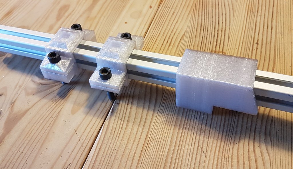
In this project I needed to make a mounting to mount various equipment to the aluminum rails. To make it easier to move the equipment the mountings need to be easy to remove , yet solid enough that they will not move by themselves.

I came up with 3 designs. The first one was a tube that was slid onto the rail. this was quickly abandoned since we would then have to take the box apart to be able to move the mounting from one rail to another.
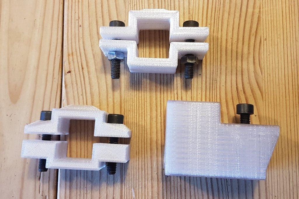
The next design was two halves that was clamped from either side, with an inner dimension of 20mm X 20mm ,plus a tolerance of 0.1 mm in only one direction, the width had to have a bit of lee way while the depth should not since this would be clamped together with the bolt.
I made two iterations of this one because I found out that it was a good idea to fix the nut. That way, you will only need one hand to tighten or loosen the mounting. Again, tolerance becomes important because We need the nut to sit tight in the hole so it wont fall out if the bolt is removed.

I find it interesting to work with these kinds of constraints, in this case I had some nuts and bolts, some aluminum rails, and some mounting requirements. I had to make my 3dprinted parts fit, either loosely or tightly, and it is really only a matter of tenth of millimeters whether it works or not.
This is not an elaborate tutorial on how to get the tolerances right in every situation. it is just a short introduction to the subject along with some of my experiences. I do hope it may prove to be educative to some of you anyway.

Im EvilHippie, a compulsive creative and jack o' trades. If you want to know more about me, check out my introduction post here
If you like what you see, feel free to upvote, follow and resteem
or you can check out these recent posts
alternative pommel
silent wood
upgrade!
pommelcasting part 2
pommelcasting part 1
