
All the work done is only valuable if you can share it with others.
The Purpose
The technical documentation, consisting out of the drawings, the parts list and other important document, is the finall result of the development. The drawings contain the most information.
It is said quite beautiful on Wikipedia:
An engineering drawing, a type of technical drawing, is used to fully and clearly define requirements for engineered items. Engineering drawing (the activity) produces engineering drawings (the documents). More than merely the drawing of pictures, it is also a language—a graphical language that communicates ideas and information from one mind to another. Most especially, it communicates all needed information from the engineer who designed a part to the workers who will make it.
Crafting technical drawings is a craft and needs a lot of proficiency. Technical drawings contain all the information needed for manufacturing the product and are the condensed wisdom of the previous work. This should be reflected in the care and detail while forging these documents.
All the previous work of development ends with the manufacturing of the documents. These are then to be handed over to manufacturing. As an entrepreneur the monitoring doesn't stop as the incentive wasn't producing documents, but to make a profit of them or the resulting product.
At the end of development, the clear instructions in the documents have to be enough to enable another person to build the product, without coming up with any questions. For this purpose, the drawings are filled with clear, information rich symbols and the standardisation indeed builds a language of its own.
The art of technical drawings will not be explained here, because it is way too extensive and because there are already multiple quality sources freely available. See for example here at the MIT, the website engineeringdrawing.org, several YouTube videos and books.
The Problem
The details that have to be cared about are quite abundant. Two basic rules have to keep their balance:
- All the information for building the product have to be in the documentation
- The technical drawings should have as few redundancy as possible.
While the first rule makes sure that the user of the documents knows what he has to do, the second rule prevent him from becoming overwhelmed. Having too many information easily then results in losing the oversight.
But applying this rules leads to the following problem:
How does the user know where the information is, if it is only found in one point in the documentation?
This is where standardisation comes into play.
Fundamentals of Standardisation
The standards declare where and what has to be found on a technical drawing. The necessary information can always be found at the same place, and redundancy is not necessary. This makes it possible to Have all the information without repetition.
Main Information
As due to standardisation, drawings convey the following critical information:
- Geometry – The object itself in different view, as is necessary to know the form.
- Dimensions – Lengths and angles, mostly in millimeters (mm) and degree (°).
- Tolerances – Tolerances of the dimensions show the allowable variation.
- Material – Material of the object in proper terminology: Not steel but proper steel grade
- Finish – Surface quality, special treatments, important for manufacturing to estimate care to detail, time and costs.
Perspectives
Presenting information has to be done in an optimal way. When studying engineering drawing, certain tricks will be learned how a drawing can convey all necessary information while preventing to be clustered with it.
Using Symmetry
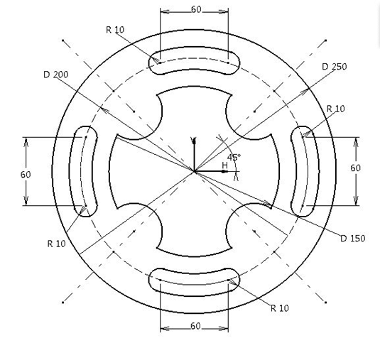
This object could be displayed with by only showing a quarter of it
Symmetrical parts can be displayed by only showing one side and giving indication about the geometry of the symmetry.
Single perspectives
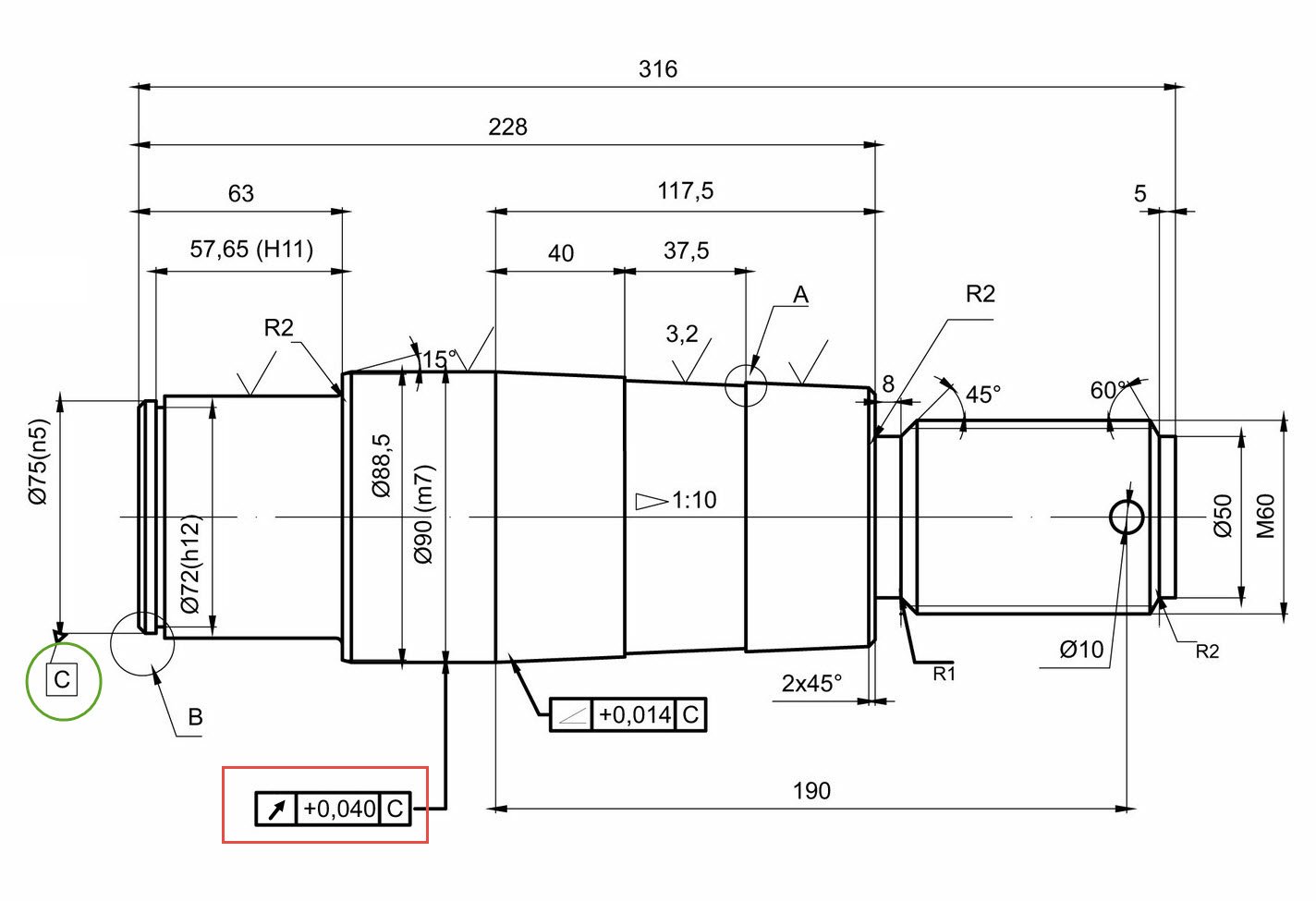
A rotation symmetrical object only needs one perspective Source
Sheet metal parts without folds can be presented in a single view, with added information about the thickness. The same goes for parts with one dimensional characteristics, like profiles.
Cutting unnecessary parts
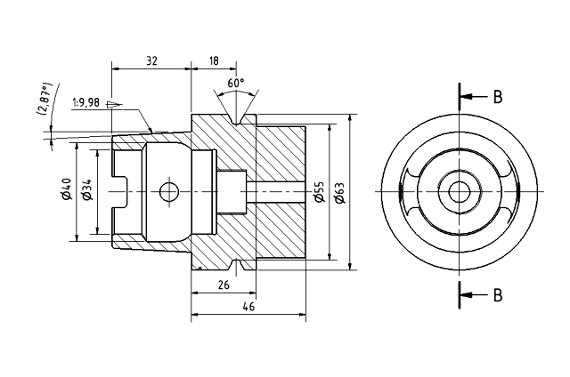
The cut opens up the view on the inside geometry. By Sven Gleich - Own work, CC BY-SA 2.5
To show hidden forms of the object, the covering parts can be cut away if they are already defined. This takes unnecessary parts out of view for better understanding of the rest of the object.
Line Types

By BAxelrod - Own work, Public Domain
Information is also conveyed in the lines. The thickness divides corners and cut surfaces, writings and measurement lines. Even the drawing of the line itself, in the single line or in the pattern gives information about the object.
Computer Aided Design
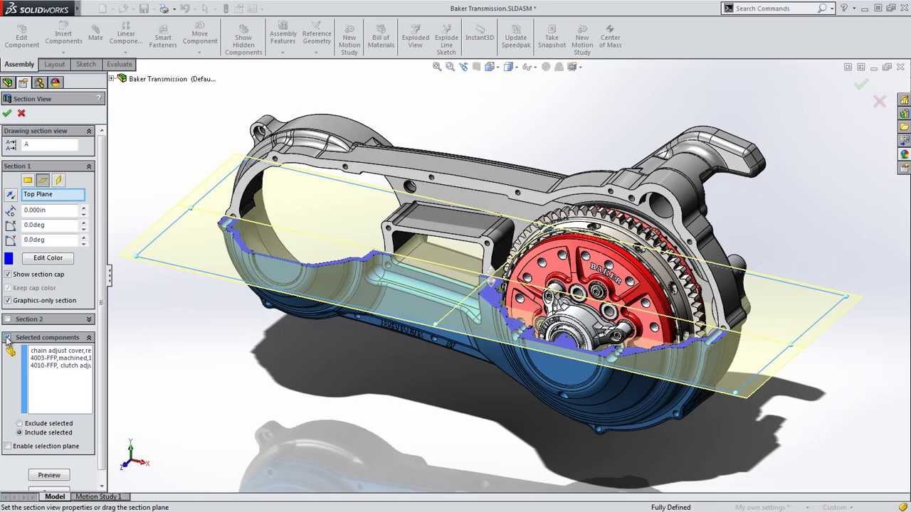
SolidWorks
With the advent of Computer-Aided Design (CAD), the work of technical drawing experienced a shift from pen and paper to the complete digital setup. With CAD it is possible to design a complete product in a virtual space and later derive the drawings directly from it.
As with all digital production, copying is very easy and changes can be done easily. No additional money has to be spend on paper, pens and drawing boards. The engineer can use only his laptop to build products. As the complexity increases, the use of a more power computer is advised.

A program with coordinates and codes for tool changes
Additional for the possibility to see the product in 3D before production, it is also important to produce files necessary to program milling machines. These used to be controlled by hand, later programmed step for step, but can now be programmed by putting in the desired form. While it is less easier than it sounds, it still is a lot less hassle than it used to be.
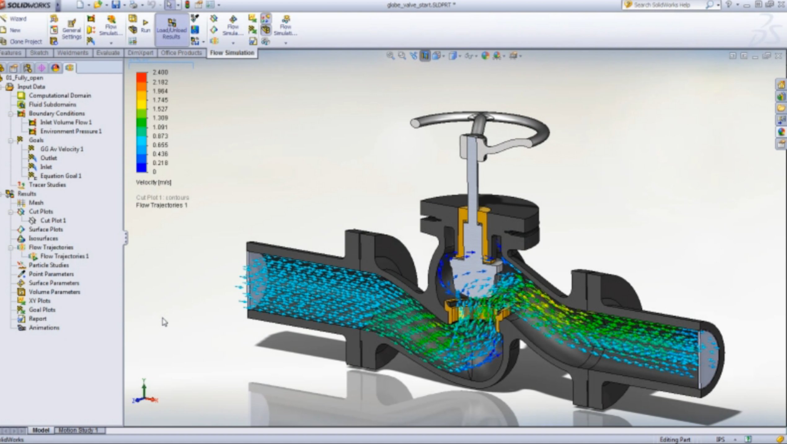
A flow analysis using SolidWorks
The 3D models further open possibilities for virtual simulation and testing, using the finite element method (FEM). This testing makes it possible to find weak points and characteristics of the product before even handing the documents over to manufacturing. This brings down costs a lot and adds to the usefulness of CAD.
Conclusion
Technical drawings connect engineers and manufacturers with its own language. Learning this skill, like any other, needs a lot of practice and care, and thus adds to the high value of the work of an engineer. The result makes the ideas, planning, calculations and design accessible to others.
CAD further expands the options by reducing cost and delivering a virtual object which can be used for testing, presentation and programming of the machines in manufacturing.
Thank you for reading!
To be continued
Further reading:
MIT Open course ware: Design Handbook: Engineering Drawing and Sketching
Engineeringdrawing.org,
Introduction to engineering drawing by EzEd
Hoischen: Technisches Zeichnen: Grundlagen, Normen, Beispiele, Darstellende Geometrie. Fachbuch
Did you already read…
Part I: What does an Engineer do?
Part II: The first STEP on the way to YOUR Product: Inventing
Part III: The Other Kind of Research: Put your IDEA into the World
Part IV: The Requirement List: The ENGINEERS way of TAKING AIM
Part V: Function Analysis: No Maths but still solving Problems
Part VI: Part Solutions: Solving one function after another
Part VII: Combined Solutions or How to build a spaceship
Part VIII: Comparing Combined Solutions: What is the best spaceship?
Part IX:Embodiment Design - Part 1: The Basic Rules and Principles
Part X:Embodiment Design Part 2: Guidelines for Design