After going on about the importance of drawings, a little guidance is needed: What has to be done to produce a technical drawing.

Getting ideas out of your head is no magic
1. Which Drawings are needed: Product - Group - Component
If the complete product is available in CAD, it is easy to separate it into its components. But even when having the construction done traditionally, there should be a good overview over all components.
The first step it to decide what needs to be drawn. Overall every part has to be drawn that also has to be manufactured. That means that norm parts are excluded. The main drawing is the end product, which is then structured into groups and components, down to the single component.
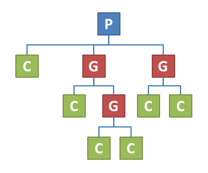
The parts tree: P for product, G for group and C for component
A drawing has then to be made of every component, group and of course the complete Product. For better overview of the work, it can be separated into modules. In the industry this can be beneficial for division of labor.
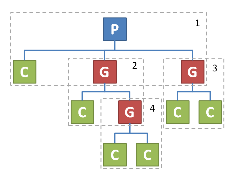
Part tree separated into modules
It can be viewed like this:
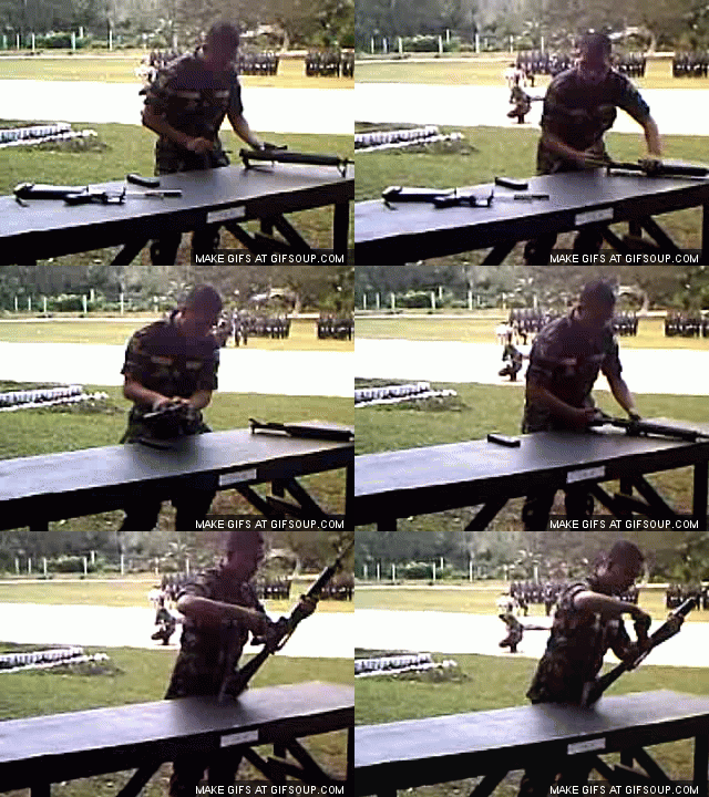
Product - Rifle
Group - Lower reciver, upper reciever, trigger group, stock
Component - Barrel, trigger and all the other small parts that are combined to the groups and product.
2. Deciding how to draw: Perspectives
After choosing what has to be drawn, the perspective is important. The more symmetrical the object is the fewer perspectives it needs. For a rotatory symmetrical object only one view might be needed, and it could also be cut in half. A metal sheet can be drawn just with the cut out and noting the thickness of the metal.
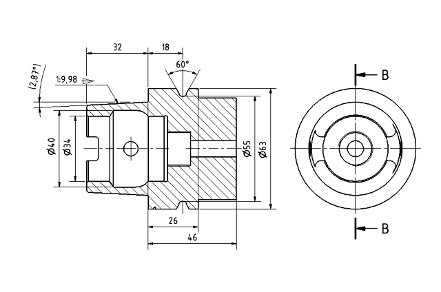
A round object (a tool mount used for milling machines), that is cut in the middle to lay open the inner contours. Notice the Bs on the right drawing, pointing on the plain and showing the viewing direction.
Again it is important to mention that redundancy has to be avoided.
3. Choosing paper dimensions and orientation
It is now known how much space is needed. This will decide which size of paper should be used. Single components might fit on a single DIN A4 page, while the complete product might need the complete size of a DIN A3.
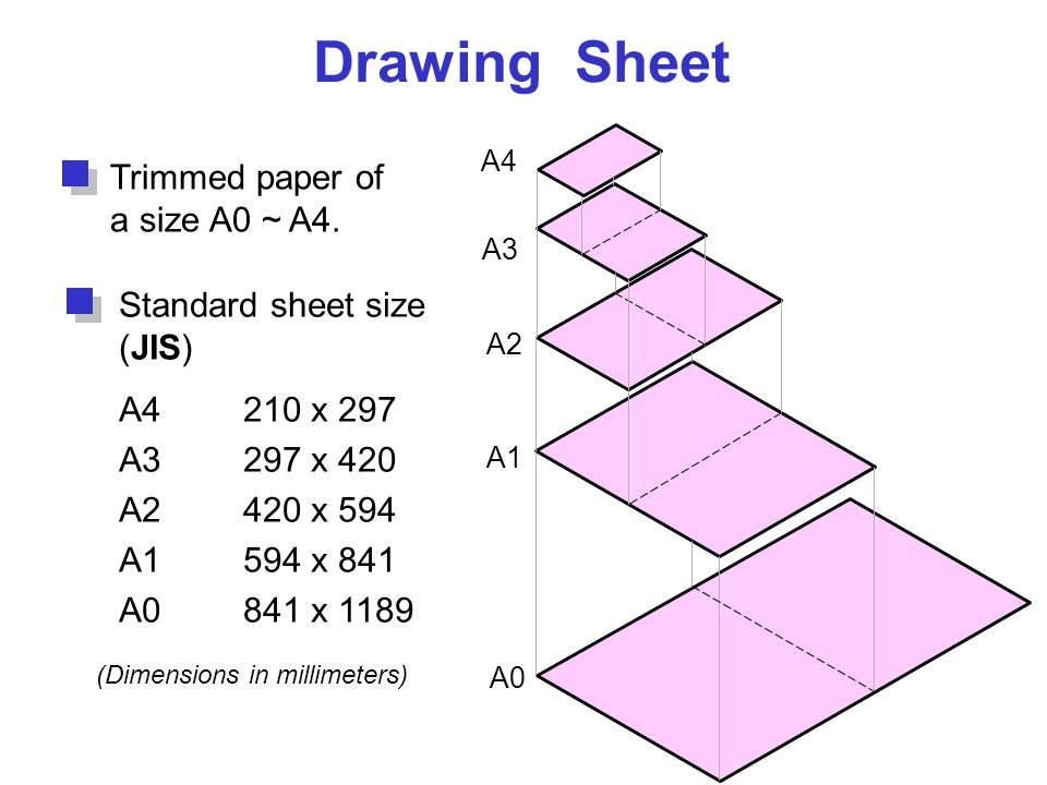
The different paper sizes after DIN. Other types can be used too.
Important mention: A part doesn't have to be drawn to scale. Regarding a lot of products this might not even possible, because they are either way bigger than a sheet of paper or might be smaller than the line.
This leaves the options to chose from at:
- Paper size (normed of course)
- Horizontal or vertical
- Scale
Normed papers have to be used, because it will have all the information where it is expected by the standardisation.
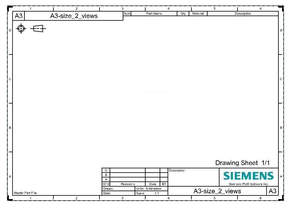
A drawing sheet with all necessary markings.
Notice that the paper is seperated into grids from A to D and 1 to 6. Also important is the drawing in the upper left corner under the headline. It indicates the projection of the drawings: The cone is seen from top on the left and tilted to the left on the right of the drawing.
4. Drawing it
While CAD makes it pretty easy to draw the part, it doesn't mean that drawing by hand is outdated. The benefit of drawing by hand is that you get a closer look onto the part and have a chance to spot errors.
The drawing process can be separated into 4 steps:
- Draw the object with fine lines, so that errors can be fixed easy.
- Adding cut aways to view hidden contours.
- Drawing patterns on cuts and special surfaces.
- Retracing all lines in the right thickness and line type (for example interrupted lines for hidden contours).
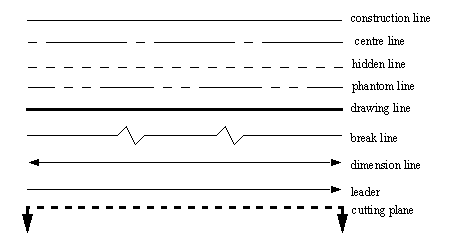
Notice the different line types, all with their own purpose
5. Measurements
With the object being drawn clean on the paper, all measurements can be added. Without redundancy here means that only so much has to be marked, that all other possible contours can be derived from them.
This process has 4 important parts:
- Measurements
- Angles
- Explanations (for example sizes of bores and threads)
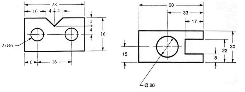
Two different kinds of measuring: Left in series and right in parallel.
6. Surfaces and Tolerances
With all measured out, special surface treatments have to be marked. In the corner of the drawing the overall surface treatment and quality is noted as well as the Tolerances. That means that they are valid unless a special requirement is given.
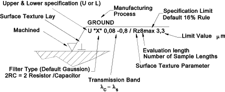
A surface marking can contain an abundance of information
The surface roughness and tolerances are important for manufacturing because they decide what machining method can be used. This is reflected then in price and manufacturing time, and even might be outside of some manufacturers possibilities.
7. Names dates and other informations
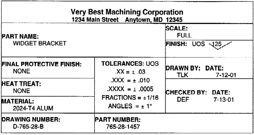
A title block with all information needed for a widget bracket
With all the information put into the drawing field, the title block has to be filled out. This field is mostly found in the bottom right corner. What can also be found in the drawing for the group and complete product besides the title block is a parts list as well as a list where the date and notes for revisions are given.
In the title block the following information can be found:
- Name of the responsible engineer
- Date
- Part name
- Part Number
- Drawing title (hence the name "title block")
- Drawing number
- Material
- Name of the corporation, government agency, etc.
- Address of the design activity (such as city, state/province, country)
- Measurement units of the drawing (for example, inches, millimeters)
- Default tolerances for dimension callouts where no tolerance is specified
- Boilerplate callouts of general specs
- Intellectual property rights warning
Most of the information should be given. Only under special circumstances should one or more things be left out. Or maybe just because they are unimportant for the manufacturer.
8. Printing and Folding
While the drawing might also be send to the supplier electronically, it is still worth printing it out. If the work was done by hand, it should be in the constructors own intention to handle the papers properly.
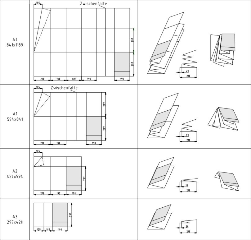
For each normed paper size exists a normed folding technique. The result is an easy storable and accessible drawing, with the title block visible without unfolding.
Folding the documents properly gives it the finishing touch and honours the work put into them, not only while drawing, but also all the development that has been done before.
The only thing missing now is the parts list. But this will be the focus in the next article.
Thank you for reading!
to be continued
Did you already read…
Part I: What does an Engineer do?
Part II: The first STEP on the way to YOUR Product: Inventing
Part III: The Other Kind of Research: Put your IDEA into the World
Part IV: The Requirement List: The ENGINEERS way of TAKING AIM
Part V: Function Analysis: No Maths but still solving Problems
Part VI: Part Solutions: Solving one function after another
Part VII: Combined Solutions or How to build a spaceship
Part VIII: Comparing Combined Solutions: What is the best spaceship?
Part IX:Embodiment Design - Part 1: The Basic Rules and Principles
Part X:Embodiment Design Part 2: Guidelines for Design
Part XI:To share IDEAS with OTHERS: Engineering Drawings
