How are you doing today? I hope everyone's having a good time. Moving deep further into the Fall season, the weather is somewhat perfect, making it easier to saty productive. However, a few setbacks and some extra work kept me from blogging for more than a week. Thankfully I found some free time and decided to add another part to this series. Life is good and business comes first, so let's waste no more time and get straight to the point!
As promised in a previous Cartography post regarding the key features and characteristics of isarithmic analysis, this is the twenty-third part of this Introduction to Cartography series. This time I am taking the chance to share general technical information regarding Choropleth maps, which is another category of Thematic maps. After having discussed the basic elements and the process followed in the creation of Isarithmic maps, we are now ready to proceed to the next category of Thematic maps. We will talk about the types of Choropleth maps and share broad information regarding the key elements of Choropleth mapping, so stay focused!
This is a personal note for all of you who are new to this blog; this is an introductory series about Cartography, which is the scientific field of, gathering measurements and processing information in order to create accurate 2D depictions of our 3D world. This means that I am presenting technical information in a simplified manner, so that nobody gets bored to death! There's a high chance of learning a thing or two by reading through this post, so stay tuned!

Symbolization Problems
Chloropleth and Isarithmic maps bare many similarities and share many common characteristics. However there is one fundamental difference which lies in the collection of data for the creation of the map. As explained in the previous parts of this series, in order to create an isarithmic map we need to collect spatial data that refers to specific points in space, the location of which is precisely known through measurements. On the contrary, the process followed when building a choropleth map induces the need for the availability of surface data. Choropleth maps represent statistical surfaces with the utilization of surface symbols.
It is worth noting at this point that the surface symbols used are placed precisely in order to represent areas where data was extracted and acquired through observations and measurments. This creates a uniformal visual outcome regarding the units utilized for the acquizition of data. There are two main methods that are most commonly followed, known as the simple choropleth projection and the unclassed choropleth projection. Both methods include the very same elements; the shape and size of surface units, the number of classes and the process followed to define the boundaries between classes. Let's take a deeper look at the two different kinds of chloropleth projections.

Simple Choropleth Maps
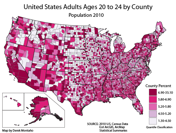
Even though gathering statistics in mathematical tables in order to make precise estimations and design solutions to a problem can be a quite effective strategy, Cartographers often have to 'paint pictures' by utilizing the information provided by measurements, which by the way can be a very effective approach. This is more of an artistic approach than a scientific statement. The primary objective is the creation of visual representations of the geographic distribution of the phenomena and entities being studied, in order to depict statistical elements and their frequency of appearance within the boundaries of the chosen surface units. And here's why simple choropleth maps are rather useful in such cases; a simple choropleth map is a spatially arranged depiction of the statistical element that refer to the surface units being used.
The techniques that are most commonly used in the creation of simple choropleth maps can also be used for various different types of ratios. The utilization of small statistical units induces large variability which results in a visual outcome that resembles a continuous distribution. However, it is worth noting at this point that the simple choropleth process is only used when any other type of projection would involve technical complexities. In fact, simple choropleth maps depict the spatial arrangement of statistical data quite efficiently, however no conclusions can be reached regarding the precise 2D location of the statistical elements being represented, as the values being mapped refer to the mean value of a spatial characteristic on a surface unit. That said, simple choropleth maps can provide Engineers with a quick 'sketch' of a spatial distribution.
Unclassed Choropleth Maps
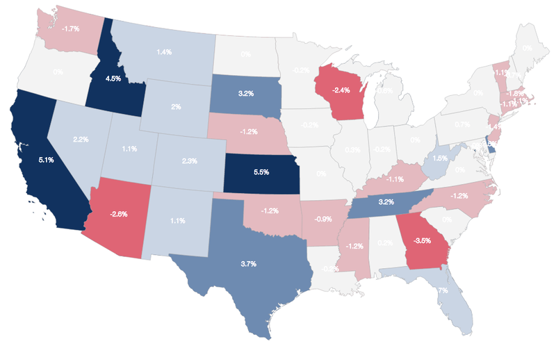
Cartographers would only use unclassed choropleth maps for a very long time, mainly due to the fact that companies were only interested in the creation of maps that could depict each characteristic's value on a continuous scale with the utilization of unique gradings for each value. This was a really tough endeavour, especially because it was pretty hard to accomplish an effective visual outcome with the given methods, techniques and equipment. As a result, color gradings could not be depicted precisely, something that is totally possible nowadays, given all the technological tools available. Unclassed choropleth maps are representations built with an analog scale which provides observers and users with a more generalized view of the spatial elements being studied and represented.
The efficiency of an unclassed choropleth map depends on many factors and cannot be compared to the efficiency of a simple choropleth map, due to the fact that the process of map generalization that was followed for the creation of the end product is rather different in each case. Unclassed choropleth projections are most commonly used due to the fact that they can provide the observer with a view of the complexity of the data utilized. It is common knowledge that normalized images generated by remote sensing devices are actually unclassed choropleth maps. Isn't it? Each pixel is described by a numerical value that refers to the characteristic being studied. Due to the nature of the human sensory system, we are not capable of observing the total number of different classes included in a normalized image. This is where the process of map generalization comes into play. More information on this in the next part. Thank you for being here!
Alright everyone, that's it for today. Another part of my beloved Introduction to Cartography series has come to an end. There's still plenty of stuff to talk about. If you do have any questions regarding anything you read here, please do let me know in the comments below and I will do my best to respond in detail. More Engineering stuff regarding Cartography and Geology coming out within the next days, so stay tuned and follow me for more!
PREVIOUS PARTS OF THE SERIES:

IMAGE SOURCES:
REFERENCES:
University Textbooks & Course Lectures:
- Χαρτογραφία Ι/ Cartography I -TSOULOS(National Technical University of Athens, School of Rural & Surveying Engineering, Course Lecture Notes)
Internet Links:
https://prism.ucalgary.ca/bitstream/handle/1880/45758/2001-693-16.pdf?sequence=2&isAllowed=y
https://gisgeography.com/choropleth-maps-data-classification/
